
A milling machine is a machine tool that removes material from a workpiece by means of a rotating multi-point cutting tool. The cutter spins at high speed while the workpiece is held stationary or moved relative to the tool along one or more axes. The result is a controlled shape, surface, or feature cut from solid stock.
This kinematics is the opposite of turning. On a lathe the workpiece rotates and the tool remains essentially stationary. On a milling machine the tool rotates and the workpiece (or the tool itself) is translated or rotated under numerical or manual control.
Basic Working Principle
Material is removed by the intermittent engagement of the cutter’s teeth with the workpiece. Each tooth shears a small chip. The depth of cut, feed rate, and spindle speed determine the volume of material removed and the resulting surface finish.
The relative motion between tool and workpiece is produced by the machine’s axes. In the simplest case three linear axes (X, Y, Z) allow the tool to reach any point in a rectangular volume. Additional rotary axes expand the range of orientations that can be machined in a single setup.
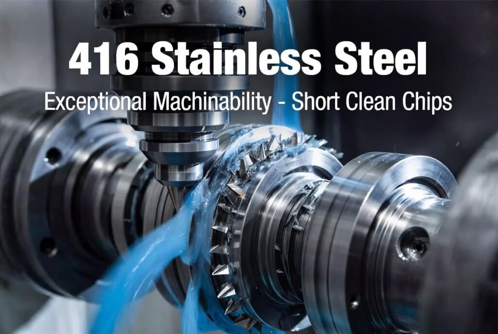
Coolant or air blast is normally applied to control temperature, flush chips, and protect the tool and workpiece surface.
Essential Components
Most milling machines share a common set of functional elements:
- Base and column – rigid structure that absorbs cutting forces and maintains geometric accuracy.
- Spindle – rotating assembly that holds and drives the cutting tool. Spindle orientation (vertical or horizontal) defines the basic machine type.
- Table or workholding surface – supports the workpiece and provides motion in the linear axes.
- Feed system – ballscrews, linear motors, or manual leadscrews that move the table or spindle.
- Control system – on CNC machines, the computer that interprets G-code and coordinates all axis motion, spindle speed, and auxiliary functions.
Tool holders (BT, CAT, HSK, etc.) secure the cutter in the spindle with sufficient rigidity for the intended cutting loads.
Vertical and Horizontal Configurations
Vertical milling machine – the spindle axis is perpendicular to the table. Gravity assists chip fall in many operations. Setup and visibility are straightforward. Vertical machines dominate general-purpose and mold work.
Horizontal milling machine – the spindle axis is parallel to the table. Chips evacuate more readily under gravity, which is advantageous for heavy roughing and deep cavities. Horizontal machines often incorporate pallet changers for higher productivity on prismatic parts.
Both configurations can be equipped with rotary tables or tilting heads to increase the number of accessible faces.
Axes of Motion
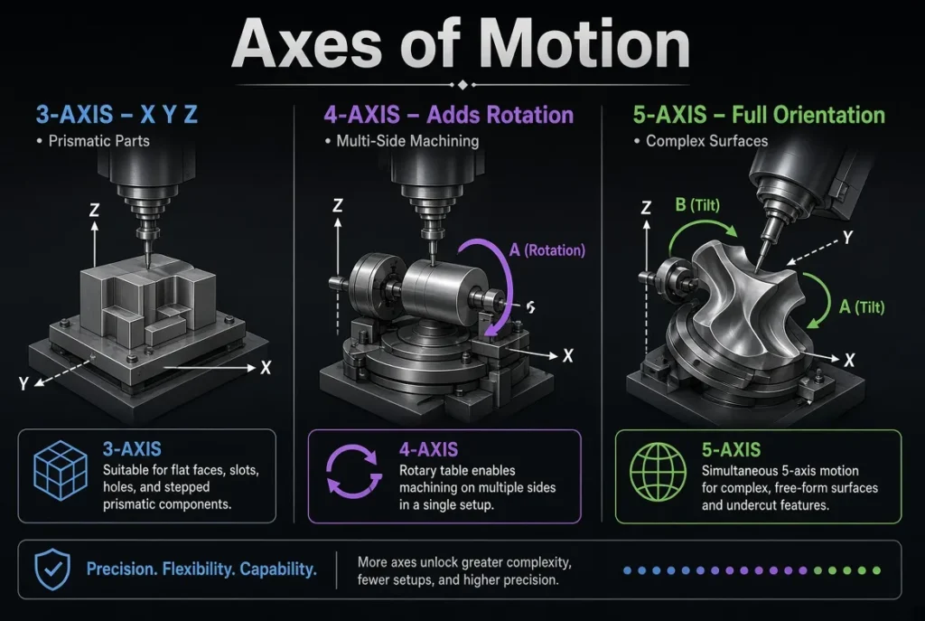
- 3-axis – X, Y, Z linear motion. Suitable for prismatic parts whose features lie primarily on one or two faces.
- 4-axis – adds one rotary axis (usually A or B). Allows machining of multiple sides of a part or continuous rotation for cylindrical features.
- 5-axis – two rotary axes in addition to the three linear axes. Simultaneous or positional 5-axis capability enables complex free-form surfaces and single-setup machining of multi-sided components.
The Z-axis is conventionally defined as parallel to the spindle axis, with the positive direction pointing away from the workpiece.
CNC versus Manual Milling
A manual milling machine relies on the operator to set feeds, speeds, and positions using handwheels or simple power feeds. Accuracy and repeatability depend heavily on operator skill.
A CNC milling machine (commonly called a machining center when equipped with automatic tool change) executes a pre-written program. The controller coordinates all motions, maintains programmed feed rates and spindle speeds, and can incorporate probing, tool-length compensation, and adaptive control. CNC systems deliver higher geometric complexity, tighter process capability, and consistent results across batches.
Typical Operations
Milling machines perform face milling, peripheral milling, slotting, pocketing, contouring, drilling, boring, and tapping. With appropriate tooling they also produce 3D surfaces, threads, and specialized features such as undercuts or helical paths.
The process is subtractive: the final part is the volume that remains after material has been removed from the original stock.
Boundaries and Practical Limits
Milling is most efficient for prismatic and moderately complex 3D shapes. Purely rotational parts with continuous cylindrical features are usually better suited to turning. Very large or heavy components may require specialized portal or gantry mills. Extremely hard materials or ultra-fine tolerances may push the process toward grinding or other secondary operations.
Internal corners cannot be sharper than the radius of the cutting tool. Deep cavities are limited by tool reach, rigidity, and chip evacuation.
FAQ
Q: Is a machining center the same as a milling machine?
A: A machining center is a CNC milling machine that typically includes automatic tool changing and often additional axes or pallet systems. All machining centers are milling machines; not all milling machines are machining centers.
Q: Can a milling machine make round parts?
A: Yes, through circular interpolation or by using a rotary axis, but continuous cylindrical features are usually produced more efficiently on a lathe.