

A fillet is a rounded transition with a defined radius. A chamfer is a flat, angled bevel, most often 45°. Both remove a sharp corner, but they solve different engineering problems and carry different manufacturing consequences.
In CNC-machined parts the choice affects stress distribution, fatigue life, tool selection, cycle time, cost, and assembly behavior. The decision should be driven by function, not habit.
Geometry and How Each Is Produced
A fillet replaces a sharp corner with a continuous arc. The radius can be constant or variable. Internal fillets are concave; external fillets are convex.
A chamfer replaces the corner with a straight angled face. It is defined by angle and leg length (for example 1 × 45° or C0.5).
In CNC milling, internal corners cannot be sharp. Every end mill leaves a radius equal to its own corner radius. Designers therefore specify an intentional fillet that is at least as large as the tool that will machine the feature. External fillets usually require a dedicated corner-rounding tool or a 3D ball-nose path. Chamfers are cut with a standard chamfer mill, countersink, or even the corner of an end mill in a single linear pass.
Stress Concentration
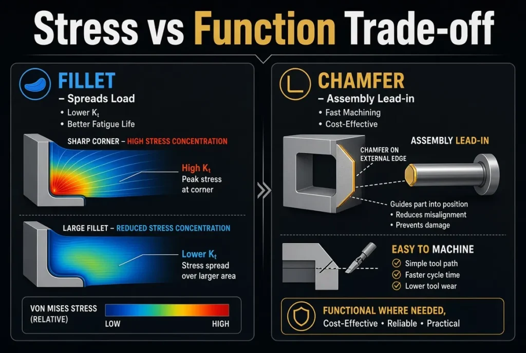
Sharp internal corners create high local stress. The stress concentration factor (Kt) for a sharp 90° corner typically falls in the range 2.5–3.0.
A fillet spreads the load along a curved surface. Larger radius relative to the section thickness produces lower peak stress. A fillet with radius equal to roughly 0.2 times the relevant dimension can reduce Kt to the 1.2–1.3 range. This reduction is the primary reason fillets are required on load-bearing or fatigue-critical transitions.
A chamfer improves the situation compared with a sharp edge but does so less effectively. It replaces one sharp corner with two milder ones. The stress reduction is real but moderate—typically bringing Kt into the 1.5–2.0 range for a 45° chamfer. Under cyclic loading the difference in fatigue life between a proper fillet and a chamfer can be substantial.
Rule of practical design: place fillets at any internal corner that carries bending, torsion, or repeated load. Use the largest radius the geometry and mating parts will allow.
Machining Cost and Tooling Reality
Chamfers are faster and cheaper in almost every external application. A single 45° chamfer tool can produce a wide range of sizes. The toolpath is a simple linear or circular pass at relatively high feed. Cycle time per edge is measured in seconds.
External fillets require either a matching radius cutter or a ball-nose tool following a 3D path with controlled step-over. Both approaches increase programming time, reduce feed rates, and raise tool wear. Relative cost for an external fillet is commonly 1.5–3 times that of a comparable chamfer; complex 3D surface fillets can be higher still.
Internal fillets that match the tool radius add almost no extra cost—they are the natural result of milling. Specifying an internal radius smaller than the available tool forces a smaller cutter, longer reach, or additional operations, all of which raise cost.
Standardizing fillet radii across a design (for example using only R1, R2, R3, R6) reduces tool changes and improves quoting accuracy.
Assembly and Functional Behavior
Chamfers excel at guiding parts together. A small chamfer on a hole entrance or shaft end acts as a lead-in, reducing the chance of binding or edge damage during assembly. Thread starts, pin holes, and mating interfaces almost always benefit from a chamfer.
Fillets provide a smoother tactile edge and better coating or plating coverage because the surface is continuous. They are preferred on external edges that will be handled frequently or that require a soft visual appearance. For press-fit or precision alignment features, however, a chamfer is usually the clearer functional choice.
Selection Guidelines
Use a fillet when:
- The corner transmits load or experiences cyclic stress
- Fatigue life is a design requirement
- An internal pocket or step is being milled (match or exceed tool radius)
- Coating uniformity or soft handling edges are important
Use a chamfer when:
- The primary need is deburring or edge break on an external surface
- Assembly lead-in is required (holes, shafts, fasteners)
- Cost and cycle time must be minimized
- Inspection simplicity matters (angle and length are easier to measure than radius)
A common practical pattern on CNC parts is “fillet the inside, chamfer the outside.” Structural internal transitions receive fillets sized for stress and tooling. Non-critical external edges receive small, standardized chamfers for safety and appearance.
Design and Drawing Notes
Call out fillets with a radius value (R2, R3.0). Call out chamfers with size × angle or the C notation (1 × 45°, C0.5). Avoid mixing many different fillet radii on one part unless functionally necessary.
When a drawing shows a sharp internal corner, the machinist will still leave a tool-radius fillet. Explicitly specifying the intended radius prevents ambiguity and allows the shop to select the most efficient tool.
For very tight internal radii, confirm that a suitable tool can reach the feature without excessive deflection or chatter. In some cases a larger fillet or a redesigned corner is the lower-cost solution.
Summary Decision Logic
Ask two questions in order:
- Does this corner carry structural or fatigue load? If yes → fillet, sized as large as practical.
- If no → is the edge primarily for assembly guidance, deburring, or appearance? If yes → chamfer.
The choice between fillet and chamfer is therefore not a matter of preference. It is a trade-off among stress performance, tooling cost, cycle time, and functional requirements. Getting the decision right early in design avoids both over-engineering and under-performing parts.
FAQ
Q: Can I replace every fillet with a cheaper chamfer?
A: Only on non-loaded external edges. On internal structural corners the stress penalty is usually unacceptable.
Q: What is the smallest practical internal fillet in CNC milling?
A: It is limited by the smallest reliable tool that can reach the feature. Most shops prefer radii of 1 mm or larger for aluminum and 1.5–2 mm for harder steels unless the design forces a smaller size.