

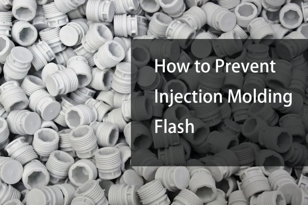
Injection molding flash is excess plastic that escapes from the intended mold cavity and solidifies along the parting line, around ejector pins, inserts, vents, or other mold interfaces. It usually appears as a thin, unwanted layer or fin on the molded part.
Flash is often treated as a molding-machine problem, but the actual cause can be anywhere in the process chain. Mold condition, clamping force, injection pressure, material viscosity, mold temperature, venting, parting-line fit, and machine setup can all contribute.
Preventing flash therefore requires more than simply increasing clamp force or reducing injection pressure. The correct approach is to identify where the material is escaping and then determine why the mold or process is allowing it to happen.
What Causes Injection Molding Flash?
Flash occurs when molten plastic enters a gap or clearance that should remain closed during injection.
Common locations include:
- Mold parting lines
- Ejector pins
- Slides and lifters
- Core and cavity interfaces
- Mold inserts
- Venting areas
- Threaded or interchangeable components
The underlying causes generally fall into four categories:
- Mold fit and condition
- Injection molding parameters
- Clamping and machine condition
- Material and part design
These factors can interact. For example, a marginal parting line may produce acceptable parts at one processing condition but flash when injection pressure or melt temperature increases.
1. Check the Mold Parting Line
The parting line is one of the first areas to inspect when flash appears.
A properly maintained mold should close sufficiently to prevent molten material from escaping between the mating surfaces. Damage, wear, contamination, or deformation can create a small opening.
Common causes include:
- Damaged shutoff surfaces
- Wear on the parting line
- Dirt or resin deposits
- Incorrect mold assembly
- Insufficient contact between mating surfaces
- Mold deformation under pressure
If flash consistently appears along the same parting line, inspect the corresponding mold surfaces before changing several molding parameters at once.
A process adjustment may temporarily reduce the symptom without addressing the underlying mold condition.
2. Use Sufficient Clamping Force
The mold must remain closed during injection.
If the injection force exceeds the effective clamping force holding the mold halves together, the mold can separate slightly and allow molten material to enter the resulting gap.
However, increasing clamp force indefinitely is not a reliable solution.
Excessive clamping force can increase stress on the mold and machine and may create other maintenance or process issues.
A better approach is to verify that the selected clamping force is appropriate for:
- Projected part area
- Injection pressure
- Mold design
- Machine capability
- Material
- Part geometry
If flash appears across a large portion of the parting line, clamping conditions should be evaluated together with mold condition and injection pressure.
3. Control Injection Pressure
Injection pressure is required to fill the mold, but excessive pressure can increase the tendency of molten material to enter small clearances.
If a part fills correctly at a lower pressure but begins flashing after pressure is increased, the process window should be reviewed.
However, simply lowering injection pressure can create:
- Short shots
- Weld-line problems
- Poor replication of fine features
- Incomplete filling
The goal is not to use the lowest possible pressure.
The goal is to use sufficient pressure to fill the cavity without creating unnecessary pressure against mold interfaces.
4. Control Injection Speed
Injection speed affects how quickly material enters the cavity and how pressure develops during filling.
A very aggressive filling profile may increase the pressure acting on weak or worn mold interfaces.
Reducing injection speed can sometimes reduce flash, but it should not be treated as a universal fix.
Changing speed also affects:
- Shear heating
- Flow behavior
- Weld lines
- Filling time
- Surface appearance
- Fiber orientation in reinforced materials
For this reason, injection speed should be adjusted as part of the overall filling strategy rather than changed only because flash is present.
5. Control Melt and Mold Temperature
Temperature affects the viscosity and flow behavior of the polymer.
When the melt becomes easier to flow, it can enter small gaps more readily.
Excessively high melt temperature can therefore contribute to flash in some applications.
Mold temperature also influences material flow and solidification.
If flash begins after processing temperatures are increased, compare the new conditions with the previous stable process before making multiple changes.
Temperature changes should always remain within the processing range recommended for the specific material.
6. Improve Mold Venting
Venting is necessary because air inside the cavity must escape as molten plastic fills the mold.
Poor venting can increase resistance to filling and create localized pressure.
A common mistake is to assume that reducing injection pressure is always the solution.
The real problem may be insufficient or poorly positioned vents.
Proper vent design needs to balance two requirements:
Allow air and gases to escape while preventing excessive polymer leakage.
Vent dimensions and locations depend on:
- Polymer
- Part geometry
- Fill pattern
- Mold design
- Injection conditions
Vents should therefore be designed and maintained as part of the mold system rather than treated as an afterthought.
7. Inspect Ejector Pins and Slides
Flash is not limited to the main parting line.
It can also form around moving mold components.
Ejector pins, slides, lifters, and other mechanisms require controlled clearances so they can move while preventing excessive material leakage.
Flash around an ejector pin may indicate:
- Excessive clearance
- Wear
- Damaged surfaces
- Poor alignment
- Resin contamination
If the flash follows a moving component rather than the primary parting line, inspect that component specifically.
8. Maintain the Mold Surface
A mold does not remain dimensionally identical throughout its service life.
Repeated molding cycles can produce:
- Wear
- Surface damage
- Corrosion
- Deposits
- Burrs
- Changes in shutoff geometry
Regular mold maintenance helps identify these problems before they become major sources of flash.
Cleaning is particularly important when resin buildup prevents mold surfaces from closing correctly.
For precision molds, maintenance should include inspection of the surfaces that establish the cavity and shutoff conditions, not only cosmetic cleaning.
9. Check Mold Alignment
The two mold halves need to meet in the intended position.
Misalignment can create uneven contact at the parting line or around inserts and moving components.
Potential causes include:
- Worn guide components
- Incorrect mold assembly
- Machine-side alignment issues
- Damaged locating features
- Mold deformation
If flash occurs more heavily on one side of the part than another, alignment and mold seating should be investigated.
10. Check for Mold Damage
A small damaged area on a shutoff or parting surface can produce a visible flash line on every molded part.
Inspect for:
- Nicks
- Scratches
- Cracks
- Burrs
- Erosion
- Deformed shutoffs
The appropriate repair depends on the location and severity of the damage.
Minor surface defects may sometimes be corrected through controlled polishing or fitting. More serious damage may require machining, insert replacement, welding and re-machining, or other mold-repair procedures.
The repair should restore the intended geometry rather than simply removing the visible flash from the molded component.
How to Prevent Injection Molding Flash During Mold Design
Flash prevention should begin before the mold reaches production.
Design Reliable Parting Lines
Parting-line geometry should provide sufficient contact and stability while allowing the mold to open and close reliably.
Complex parting lines can introduce additional shutoff surfaces and increase the number of areas that require precise fitting.
For this reason, part geometry and mold parting strategy should be considered together during design.
Design Appropriate Shutoffs
Shutoff surfaces control where mold sections meet around openings, slides, cores, and other features.
Poorly designed or difficult-to-machine shutoffs can make flash control more difficult.
Precision machining is particularly important where small geometric deviations can affect how mating mold surfaces contact each other.
Consider Draft Angles
Draft helps the molded component release from the mold.
Insufficient draft can increase the risk of:
- Part sticking
- Surface damage
- Mold wear
- Ejection problems
While draft does not directly eliminate flash, appropriate draft can reduce mechanical stress on the mold and part during ejection.
Avoid Unnecessarily Complex Mold Geometry
Every additional insert, slide, lifter, or shutoff can introduce another interface that needs to maintain controlled clearance.
Complex geometry may be unavoidable for certain parts, but it should be evaluated against:
- Mold cost
- Machining requirements
- Maintenance
- Alignment
- Flash risk
- Expected production volume
A simpler mold is not automatically better, but unnecessary complexity can increase the number of potential failure points.
How CNC Machining Affects Flash Prevention
Precision machining plays an important role in producing mold components that fit together correctly.
CNC milling, turning, EDM, and grinding may be used to manufacture or finish different mold components depending on the required geometry and material.
Critical mold features may include:
- Cavity surfaces
- Core surfaces
- Shutoffs
- Inserts
- Slides
- Mold plates
- Ejector components
The important point is that CNC machining does not prevent injection molding flash by itself.
Its role is to produce the dimensional and geometric relationships required for the mold to close, align, and operate correctly.
For example, if a shutoff surface or insert is machined incorrectly, the resulting clearance can become a direct source of flash.
How to Troubleshoot Injection Molding Flash
When flash appears, changing several process parameters simultaneously makes the root cause difficult to identify.
A more controlled troubleshooting sequence is:
Step 1: Identify the Flash Location
Determine whether the flash occurs at:
- Main parting line
- Ejector pin
- Slide
- Insert
- Vent
- Other mold interface
The location often provides the first clue about the cause.
Step 2: Check Mold Condition
Inspect the relevant surfaces for:
- Wear
- Damage
- Contamination
- Misalignment
- Resin buildup
Step 3: Review Machine Conditions
Check:
- Clamp force
- Mold mounting
- Machine alignment
- Injection pressure
- Injection speed
Step 4: Review Material Conditions
Confirm:
- Correct material
- Material preparation
- Drying requirements
- Melt temperature
- Processing window
Step 5: Change One Variable at a Time
Make controlled adjustments and record the result.
This makes it easier to determine whether the flash is caused primarily by the mold, machine, material, or process settings.
Injection Molding Flash Troubleshooting Table
| Flash Location | Possible Cause | First Check |
|---|---|---|
| Main parting line | Mold separation, wear, damage | Parting-line condition and clamp force |
| Around ejector pin | Excessive clearance or wear | Pin and bore condition |
| Around slide | Wear or alignment | Slide shutoff surfaces |
| Around insert | Poor fit or damage | Insert-to-cavity interface |
| Near vent | Excessive vent gap or process pressure | Vent condition and injection parameters |
| One side of part | Misalignment or uneven contact | Mold alignment |
| Entire perimeter | Excessive cavity pressure or mold separation | Clamp force and injection conditions |
This table is a troubleshooting guide, not a diagnostic rule. The same flash pattern can have different causes depending on the mold construction and molding process.
Can Injection Molding Flash Be Removed After Molding?
Yes. Flash can often be removed through secondary operations such as:
- Manual trimming
- Deflashing
- Cutting
- Grinding
- Tumbling
- Cryogenic deflashing in suitable applications
However, removing flash after molding should not replace correcting the underlying molding problem when the defect is recurring.
Secondary trimming adds:
- Labor
- Cycle time
- Cost
- Additional handling
- Potential dimensional variation
For production parts, eliminating the source of flash is generally preferable when practical.
How to Prevent Flash on Plastic Parts
A reliable flash-prevention strategy combines mold design, machining accuracy, machine setup, and process control.
The most important measures are:
- Maintain clean and undamaged parting surfaces.
- Verify adequate and appropriate clamping force.
- Avoid unnecessarily high injection pressure.
- Control melt and mold temperatures within the material’s recommended range.
- Provide effective cavity venting.
- Inspect ejector pins, slides, inserts, and shutoffs.
- Maintain mold alignment.
- Monitor mold wear over production life.
- Machine critical mold components to the required dimensional and geometric specifications.
- Troubleshoot based on the flash location instead of changing multiple process variables at once.
The exact corrective action depends on where the flash occurs and why the mold is allowing material to escape.
FAQ
Q: Does increasing clamp force stop flash?
A: Increasing clamp force can reduce mold separation when clamping force is insufficient, but it is not a universal solution. Excessive clamp force can create other problems, so the correct value should be determined from the mold, machine, projected area, and injection conditions.
Q: Can high injection pressure cause flash?
A: Yes. Higher cavity pressure can increase the force acting on mold interfaces and may contribute to flash when the mold has marginal shutoffs, alignment problems, or insufficient clamping conditions. However, reducing pressure too far can cause incomplete filling.
Q: Can mold temperature cause flash?
A: Mold temperature affects polymer flow and solidification. Depending on the material and process, changes in mold temperature can affect the tendency for material to enter small clearances. Processing should remain within the material supplier’s recommended range.
Q: Why does flash occur around ejector pins?
A: Flash around an ejector pin can result from excessive clearance, wear, misalignment, or damage between the pin and surrounding mold component. The ejector system should be inspected rather than simply trimming the resulting flash.
Q: Is injection molding flash a mold defect or a process problem?
A: It can be either. Flash may originate from mold wear or damage, but it can also result from injection pressure, clamping conditions, temperature, material behavior, or other process variables. In many cases, several factors contribute.