
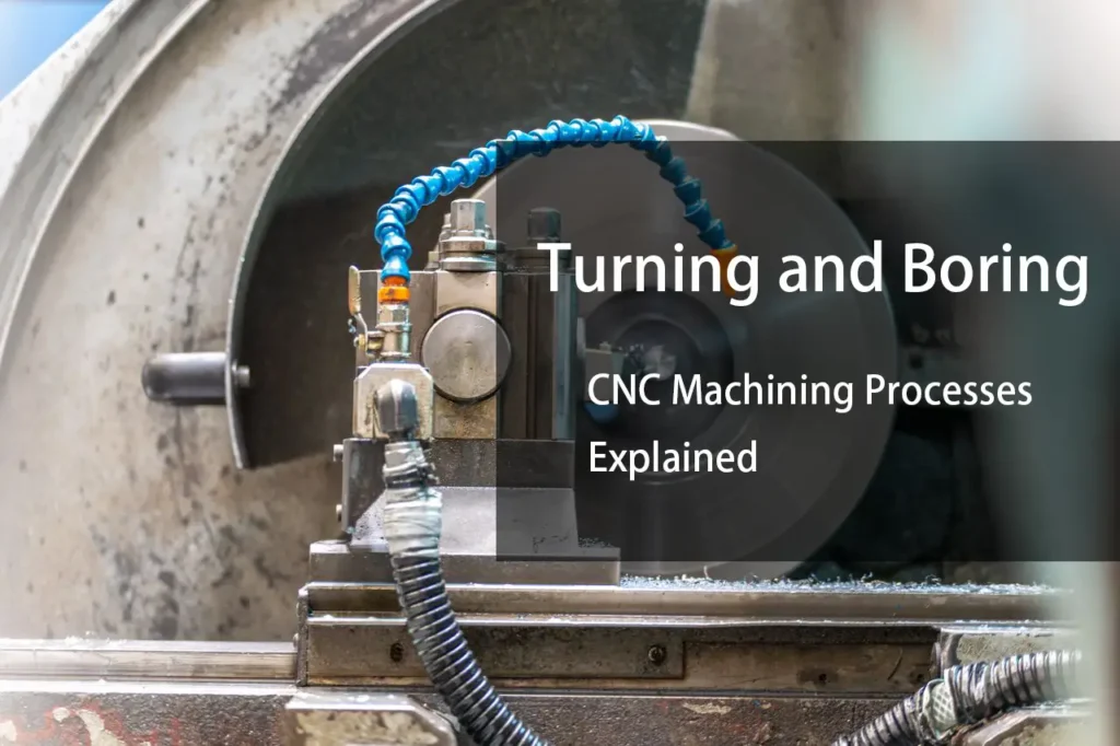
Turning and boring are two fundamental machining operations used to produce cylindrical features. They are often discussed together because both are commonly performed on CNC lathes and turning centers, but they solve different machining problems.
Turning primarily removes material from the outside diameter of a workpiece, while boring enlarges, corrects, or finishes an existing internal hole.
The distinction becomes especially important when machining precision components. The choice between turning and boring affects tool access, cutting forces, dimensional control, surface finish, and the number of operations required.
Understanding how these processes work also helps when deciding whether a cylindrical feature should be produced by turning, drilling, boring, or a combination of operations.
What Is CNC Turning?
CNC turning is a machining process in which the workpiece rotates around its spindle axis while a cutting tool moves relative to the rotating material.
The cutting tool removes material from the workpiece to produce cylindrical, tapered, stepped, threaded, or contoured features.
In a typical CNC turning operation, the workpiece is held in a chuck or another workholding system. The spindle rotates the part while the cutting tool travels along or across the workpiece.
Common turning operations include:
- Outside diameter turning
- Facing
- Shoulder turning
- Taper turning
- Grooving
- Threading
- Parting
- Contour turning
Seco Tools describes turning as a process in which the lathe rotates the workpiece while the cutting tool moves along the diameter to remove material and produce cylindrical geometry.
What Is Boring?
Boring is a machining operation used to enlarge or finish an existing hole.
Unlike drilling, which generally creates the initial hole, boring starts with an existing opening and removes additional material from its internal surface.
A boring tool normally consists of a boring bar with a cutting edge positioned to machine the inside diameter.
Boring can be used to improve:
- Hole diameter
- Roundness
- Concentricity
- Cylindricity
- Surface finish
- Positional accuracy
Haas tooling documentation, for example, identifies boring bars specifically as internal machining tools and notes that the available hole diameter limits the boring bar size that can be selected.
This makes boring fundamentally different from simply drilling a hole to a nominal diameter.
Turning vs. Boring
The simplest distinction is based on where the cutting occurs.
| Characteristic | Turning | Boring |
|---|---|---|
| Primary surface | External diameter | Internal diameter |
| Starting condition | Solid or external stock | Existing hole |
| Main tool | Turning tool | Boring bar |
| Cutting location | Outside of workpiece | Inside of workpiece |
| Typical purpose | Reduce OD / create external geometry | Enlarge or finish an existing hole |
| Tool rigidity | Generally easier to maintain | More sensitive to overhang |
| Chip evacuation | Usually easier | Can be more challenging |
| Deflection risk | Relatively manageable | Often more significant |
| Typical limitation | External tool access | Internal tool reach and rigidity |
This distinction is useful, but it does not mean that every internal feature must be bored.
A hole may begin with drilling and then be finished by boring, reaming, honing, or another process depending on the required geometry and tolerance.
How Does CNC Turning Work?
A typical turning process follows a relatively straightforward sequence.
1. Workpiece Setup
The material is secured in a chuck, collet, or other workholding system.
The setup needs to provide sufficient gripping force and rigidity while maintaining the required alignment.
2. Tool Positioning
The turning tool is positioned relative to the workpiece.
Tool geometry, insert type, nose radius, tool orientation, and cutting-edge condition all influence the machining result.
3. Rough Turning
The first passes remove the majority of the excess material.
Roughing normally prioritizes material removal and process stability rather than final surface finish.
4. Semi-Finishing
A subsequent operation can bring the component closer to the final dimensions while leaving a controlled amount of material for finishing.
5. Finishing
The final turning pass establishes the specified dimensions and surface condition.
The appropriate feed, cutting speed, depth of cut, and tool geometry depend on the material and drawing requirements.
How Does Boring Work?
Boring normally begins after a hole has already been created.
A typical sequence is:
- Produce the initial hole.
- Establish the required boring allowance.
- Insert the boring bar.
- Position the cutting edge at the required diameter.
- Remove material from the internal surface.
- Measure the bore.
- Perform a finishing pass if required.
The amount of material removed during boring can vary considerably.
A rough boring operation may remove substantial material from an oversized hole, while finish boring may remove only a small amount to achieve the final dimension and surface condition.
Why Is Boring More Sensitive to Tool Deflection?
One of the main engineering challenges in boring is tool overhang.
A boring bar has to extend into the hole to reach the internal surface. As the required hole depth increases, the bar may need to extend farther from the toolholder.
This reduces the stiffness of the tool assembly.
The result can be:
- Tool deflection
- Chatter
- Dimensional variation
- Poor surface finish
- Tapered bores
- Difficulty maintaining roundness
Sandvik Coromant’s tooling guidance highlights the relationship between boring-bar material, overhang, stiffness, and process stability. It recommends keeping the tool assembly as short as practical; its application data also shows that carbide and damped boring-bar designs can support greater overhang than conventional steel bars.
This is one reason boring deep holes is often more demanding than turning an external diameter of similar length.
Boring Bar Selection
Boring-bar selection is not simply a matter of choosing a bar that fits inside the hole.
The bar should be selected according to:
- Minimum bore diameter
- Bore depth
- Required overhang
- Workpiece material
- Required tolerance
- Surface finish
- Cutting forces
- Machine rigidity
- Coolant requirements
Steel Boring Bars
Steel bars are commonly used for shorter internal machining applications.
They are practical when the required overhang is relatively small and the machining conditions are stable.
For deeper bores, however, the available stiffness may become limiting.
Carbide Boring Bars
Carbide bars can provide greater stiffness for a given overhang than conventional steel bars.
Sandvik reports that carbide bars can provide substantially higher static stiffness than steel bars at the same overhang, making them useful for applications requiring greater reach.
The exact choice still depends on the application rather than simply choosing carbide whenever possible.
Damped Boring Bars
For long-overhang boring, vibration control becomes a major concern.
Damped boring bars incorporate a damping mechanism intended to reduce vibration and improve dynamic stability.
They can be particularly useful when conventional boring bars cannot maintain acceptable process stability at the required depth.
Rough Boring vs. Finish Boring
Boring is often divided into roughing and finishing stages.
Rough Boring
The purpose of rough boring is to remove material efficiently while establishing a controlled bore for the finishing operation.
Typical priorities include:
- Material removal
- Tool stability
- Chip control
- Productivity
- Leaving consistent finishing allowance
Dimensional accuracy is still important, but the operation does not normally need to establish the final bore condition.
Finish Boring
Finish boring focuses on the final internal geometry.
The operation may be used to achieve tighter requirements for:
- Diameter
- Roundness
- Cylindricity
- Surface finish
- Concentricity
Because only a relatively small amount of material may remain, process stability and tool condition become particularly important.
Turning and Boring on the Same CNC Lathe
Modern CNC turning centers can often perform both external turning and internal boring during the same setup.
This is useful because the machine can establish external and internal features while maintaining a common workholding reference.
A typical component may therefore use:
- Facing
- OD rough turning
- OD finishing
- Drilling
- Rough boring
- Finish boring
- Grooving
- Threading
- Parting
The exact sequence depends on the part geometry and datum strategy.
Combining operations in one setup can reduce the need to re-fixture the component, but it does not automatically guarantee better accuracy. Workholding deformation, spindle alignment, tool deflection, thermal effects, and measurement strategy still affect the result.
When Should You Use Boring Instead of Reaming?
Boring and reaming can both be used after drilling, but they serve different purposes.
Boring removes material with a single-point cutting tool and gives the machinist direct control over the internal diameter through the tool position.
Reaming uses a multi-edge tool designed to finish an existing hole to a specific size and surface condition.
Boring may therefore be preferable when:
- The hole diameter needs adjustment
- A larger hole is required
- Different diameters must be produced
- Bore alignment is important
- The feature requires controlled internal geometry
Reaming can be efficient when a suitable standard reamer can produce the required final condition in a stable production process.
The correct choice depends on the drawing requirements rather than the assumption that one process is universally more accurate.
Boring Challenges in CNC Machining
Chatter
Chatter is one of the most common problems in internal machining.
The risk increases when:
- Boring-bar overhang is excessive
- The bar diameter is too small
- Cutting forces are high
- Workholding is insufficient
- Cutting parameters are poorly matched to the setup
The first response should generally be to improve the stiffness of the cutting system rather than simply changing one cutting parameter.
Reducing overhang and increasing boring-bar diameter where the bore permits are fundamental measures.
Bore Diameter Variation
An internal diameter may vary along its depth.
Possible causes include:
- Boring-bar deflection
- Thermal effects
- Tool wear
- Machine alignment
- Insufficient setup rigidity
- Inconsistent cutting conditions
A bar that deflects during cutting may not return to the programmed path, resulting in a bore that is not perfectly cylindrical.
Poor Surface Finish
Poor bore finish may result from:
- Excessive feed
- Tool vibration
- Worn insert
- Incorrect nose radius
- Unstable cutting conditions
- Poor chip evacuation
For finish boring, the cutting edge must remain stable throughout the operation.
A tool that produces acceptable roughing results may not necessarily be appropriate for finishing.
How to Improve Boring Accuracy
Several practical measures can improve internal machining stability.
Keep the Boring Bar as Short as Possible
Shorter overhang generally means greater stiffness.
The tool should extend only far enough to reach the required feature.
Use the Largest Practical Bar Diameter
The bore diameter limits the maximum bar diameter, but using a larger bar within that clearance generally improves rigidity.
Haas tooling guidance explicitly notes that hole diameter is a limiting factor when selecting a boring bar and recommends using a bar diameter appropriate to the available bore.
Consider Carbide or Damped Tooling
When the required overhang becomes large, a conventional steel bar may no longer provide sufficient stiffness.
Carbide and damped boring systems can extend the practical operating range.
Control Cutting Forces
Cutting conditions should be selected for the actual material, tool geometry, and setup.
Increasing productivity without considering tool rigidity can create a process that looks efficient on paper but produces unstable bores.
Measure the Bore
For precision components, the finished bore should be inspected using an appropriate measurement method.
Depending on the tolerance and application, inspection may involve:
- Bore gauges
- Internal micrometers
- Plug gauges
- CMMs
- Air gauges
- Other specialized metrology equipment
The inspection method should correspond to the engineering requirement.
Internal Turning vs. Boring
The terminology around internal machining can sometimes create confusion.
Internal turning is a broader term describing machining operations performed on the inside diameter of a component.
Boring is one of the principal internal turning operations and normally refers to machining an existing hole with a boring tool.
Other internal operations may include:
- Internal grooving
- Internal threading
- Internal profiling
- Internal chamfering
This distinction matters because a CNC turning center may perform several different internal operations using different tools.
Turning and Boring for Different Part Geometries
Shafts
Turning is commonly used for external cylindrical features such as:
- Shafts
- Pins
- Bushings
- Spacers
- Rollers
Bushings
Bushings often require both OD turning and ID machining.
A typical process may involve:
OD turning → drilling → boring → finishing
The relationship between the OD and ID may also be important for concentricity.
Flanges
Flanged components may require:
- Facing
- OD turning
- Shoulder turning
- Drilling
- Boring
- Grooving
The exact sequence depends on how the component is held and where the critical datums are located.
Deep Bores
Deep internal holes are particularly demanding because tool reach increases.
The main concerns become:
- Boring-bar rigidity
- Vibration
- Chip evacuation
- Coolant delivery
- Bore straightness
- Tool access
This is where specialized boring-bar systems may provide an advantage.
Turning and Boring Cutting Parameters
There is no single set of cutting parameters that applies to all turning and boring operations.
The appropriate values depend on:
- Workpiece material
- Tool material
- Insert geometry
- Tool diameter
- Workpiece diameter
- Depth of cut
- Feed rate
- Cutting speed
- Tool overhang
- Machine rigidity
- Coolant strategy
For boring, tool rigidity becomes an additional constraint.
A cutting condition that works well for external turning may become unstable when applied internally with a long boring bar.
This is why boring parameters should be developed around the actual tool assembly rather than copied directly from an OD turning operation.
Tool manufacturers such as Sandvik and Seco provide application-specific cutting guidance because cutter geometry, material group, engagement, and tool setup all affect the recommended conditions.
Common Mistakes in Turning and Boring
Treating Boring Like Drilling
A boring bar is not simply another type of drill.
Drilling creates the initial hole through a rotating multi-edge tool. Boring modifies an existing hole using a cutting tool that follows the internal surface.
The process mechanics and tooling requirements are different.
Using Excessive Boring-Bar Overhang
This is one of the most common causes of unstable internal machining.
If the bar is unnecessarily long, stiffness is sacrificed without providing any machining benefit.
Choosing a Bar That Is Too Small
A smaller bar may provide more clearance, but it also reduces rigidity.
The largest practical boring-bar diameter should generally be considered when the feature allows it.
Using the Same Strategy for Roughing and Finishing
Roughing and finishing have different objectives.
Roughing prioritizes material removal and stability. Finishing prioritizes dimensional control and surface quality.
Ignoring the Workholding System
A rigid boring bar cannot compensate for an unstable workholding setup.
Chuck condition, jaw engagement, fixture rigidity, part geometry, and unsupported length can all affect the final result.
FAQ
Q: What is the difference between turning and boring?
A: Turning generally machines the outside diameter of a rotating workpiece, while boring machines the inside diameter of an existing hole.
Q: Can a CNC lathe perform both turning and boring?
A: Yes. CNC turning centers commonly support both external turning and internal boring operations, along with drilling, grooving, threading, and other operations depending on the machine configuration.
Q: Is boring more accurate than drilling?
A: Boring can provide greater control over an existing hole’s diameter and internal geometry than conventional drilling, but achievable accuracy depends on the machine, tooling, workholding, material, and process conditions.
Q: Can boring create a hole from solid material?
A: Boring normally requires an existing opening. A drill or another holemaking operation is generally used to create the initial hole.
Q: How can boring-bar vibration be reduced?
A: Reduce tool overhang, use the largest practical bar diameter, improve workholding, optimize cutting conditions, and consider carbide or damped boring-bar systems for long-reach applications.
Conclusion
Turning and boring are closely related CNC machining processes, but they address different surfaces and machining requirements.
Turning primarily creates and finishes external cylindrical geometry. Boring machines an existing internal hole to improve its diameter, geometry, and surface condition.
The biggest practical difference is tool access. External turning generally allows a relatively rigid tool setup, while boring requires a bar to extend into the component. As the bore becomes deeper, tool stiffness and vibration become increasingly important.
For precision CNC machining, the process should therefore be selected from the part geometry outward. Consider the required diameter, depth, tolerance, surface finish, material, workholding, and production volume before choosing the tooling and machining strategy.
A well-designed turning and boring process is not simply about removing material quickly. It is about maintaining a stable relationship between the machine, tool, workpiece, and inspection requirements throughout the operation.