
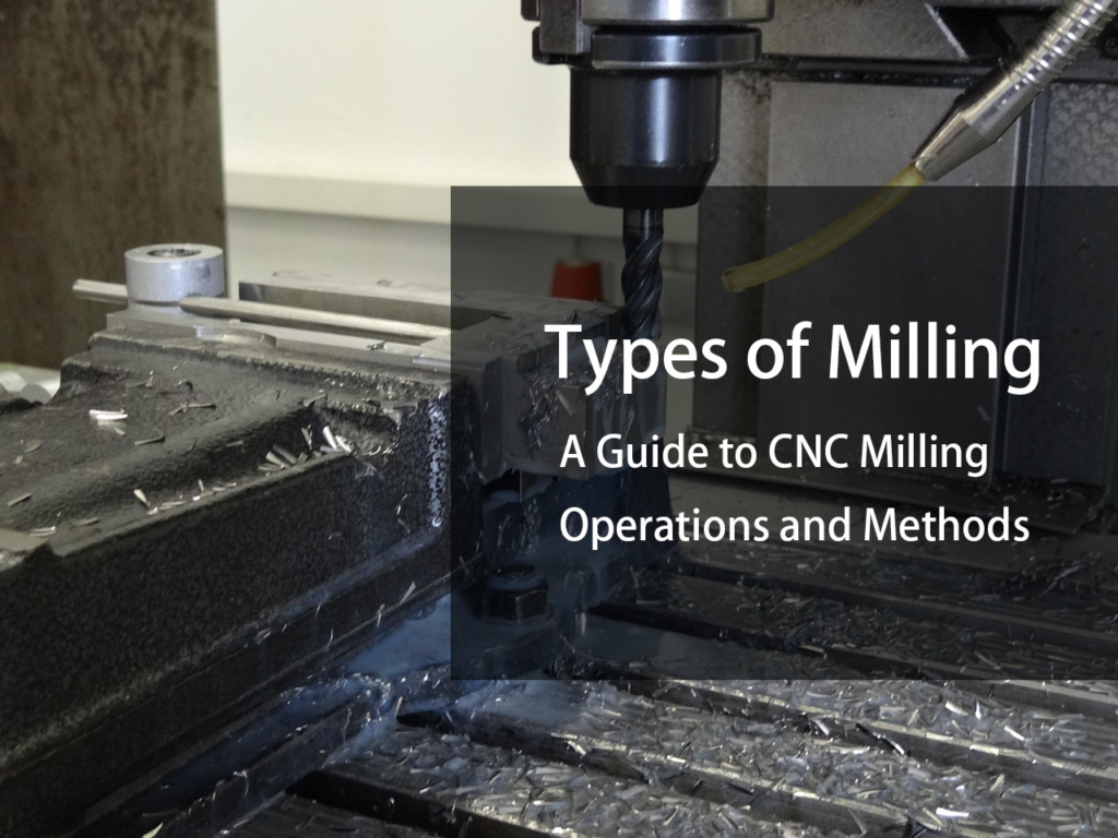
Milling is a machining process in which a rotating cutting tool removes material from a workpiece to create flat surfaces, slots, pockets, shoulders, contours, and other features. Milling operations may be classified by the cutting method, the geometry being produced, or the type of milling machine used.
For CNC machining, the most useful distinction is between milling operations and milling machine configurations. Face milling, end milling, slot milling, and profile milling describe how material is removed. Vertical, horizontal, 3-axis, 4-axis, and 5-axis machines describe the equipment and available motion used to perform those operations.
Understanding both classifications makes it easier to select a suitable machining strategy for a particular part.
What Are the Main Types of Milling?
The main CNC milling operations include:
- Face milling
- End milling
- Shoulder milling
- Slot milling
- Pocket milling
- Profile milling
- Angular milling
- Chamfer milling
- Thread milling
- Helical milling
- High-feed milling
- Plunge milling
These operations overlap in some applications. A single cutter may also perform more than one type of operation depending on its geometry and how it is programmed. Sandvik Coromant, for example, groups milling concepts into face milling, shoulder milling, high-feed milling, profile milling, and groove milling, reflecting the different machining objectives rather than a single universal classification system.
1. Face Milling
Face milling is primarily used to produce flat surfaces. The cutter rotates around an axis perpendicular to the machined surface, with cutting edges removing material across the face of the workpiece.
A face milling operation is commonly used to:
- Create a flat reference surface
- Remove material from the top of a workpiece
- Prepare a surface for subsequent operations
- Achieve a specified surface finish
- Rough or finish large planar areas
The choice of cutter depends on the required material removal, surface finish, machine rigidity, and workpiece geometry. Seco Tools notes that face milling can be performed with different cutter geometries for roughing, semi-finishing, and finishing applications.
Face milling is often one of the first operations performed when establishing a reference surface on a milled component.
2. End Milling
End milling uses a cutter with cutting edges on the end and, depending on the tool design, along its circumference.
It can be used for:
- Slots
- Pockets
- Contours
- Steps
- Cavities
- Side walls
- General material removal
End mills are available in different diameters, flute counts, helix geometries, lengths, and coatings. Tool selection depends on the workpiece material, feature geometry, depth, required finish, and cutting conditions.
End milling is therefore not a single machining strategy. It is a broad category covering many operations performed with end mills.
3. Shoulder Milling
Shoulder milling produces a relatively square transition between a machined face and a vertical wall.
A typical shoulder milling operation creates:
- 90-degree shoulders
- Steps
- Seating surfaces
- Reference edges
- Vertical walls
Square-shoulder cutters can engage the face and side of the workpiece in the same operation. This makes them useful where the relationship between the two surfaces is important. Seco describes shoulder milling as a method for producing accurate 90-degree shoulders and applications such as slotting, side milling, roughing, and machining seating surfaces.
The actual achievable geometry depends on cutter design, workholding, machine rigidity, and the specified tolerance.
4. Slot Milling
Slot milling cuts a narrow channel or groove into a workpiece.
Typical applications include:
- Keyways
- Slots
- Retaining features
- Clearance grooves
- Linear channels
- Assembly features
Slot width and depth determine the appropriate cutter. A full-width slot cut can place significant radial engagement on the tool, particularly when the cutter is engaged on both sides.
For deeper slots, chip evacuation and tool rigidity become increasingly important.
Slot milling can also be performed as part of a broader pocketing or contouring strategy rather than as an isolated operation.
5. Pocket Milling
Pocket milling removes material from an enclosed or partially enclosed area to create a cavity.
A pocket may have:
- A flat bottom
- Vertical walls
- Tapered walls
- Internal radii
- Islands
- Multiple depths
CNC pocketing is normally programmed using a toolpath that progressively removes material from the pocket area. The selected strategy depends on the pocket geometry, material, cutter diameter, required surface finish, and available machine motion.
For deep pockets, tool access becomes a major design consideration. A long tool may be required to reach the bottom, but greater tool stickout can reduce rigidity and increase the possibility of deflection or vibration.
6. Profile Milling
Profile milling follows the outside or inside contour of a component.
It is commonly used to create:
- External profiles
- Internal contours
- Curved edges
- Complex 2D shapes
- 3D surfaces
Profile milling becomes more demanding when the geometry changes continuously in three dimensions. Tool diameter, tool orientation, step-over, step-down, and machine axis capability all influence the resulting surface.
For complex components, multi-axis machining can allow the cutting tool to maintain a more suitable orientation relative to the surface.
7. Angular Milling
Angular milling produces surfaces that are inclined relative to the primary workpiece planes.
The required angle can be produced using:
- An angled cutter
- A tilted workpiece
- A rotary axis
- A multi-axis tool orientation
The appropriate method depends on the part geometry and production requirements.
For relatively simple angled surfaces, a conventional milling setup may be sufficient. More complex or multi-sided geometry may benefit from 4-axis or 5-axis machining.
8. Chamfer Milling
Chamfer milling creates a beveled edge rather than a sharp 90-degree edge.
Chamfers are commonly used to:
- Remove sharp edges
- Improve part handling
- Prepare edges for assembly
- Provide clearance
- Meet drawing requirements
- Prepare a feature for another operation
Chamfer cutters are available in different included angles. The required cutter geometry should match the drawing specification rather than being selected only according to the desired visual appearance.
For precision components, chamfer size and angle may need to be inspected just like other machined dimensions.
9. Thread Milling
Thread milling creates internal or external threads using a rotating cutter and a helical toolpath.
The cutter moves around the thread diameter while simultaneously advancing along the thread axis. One revolution corresponds to one thread pitch when the toolpath is correctly programmed.
Thread milling can be useful when:
- Different thread sizes are required
- Blind holes are involved
- The material is difficult to tap
- Thread dimensional control is important
- Tool flexibility is valuable
Thread milling also differs fundamentally from tapping because the thread is generated through CNC interpolation rather than by following the thread geometry of a tap.
10. Helical Milling
Helical milling combines circular motion with simultaneous axial movement.
The resulting toolpath resembles a helix.
It can be used to create:
- Holes
- Circular cavities
- Ramps
- Threaded features
- Interpolated bores
Helical interpolation is particularly useful when a hole diameter is larger than the available cutter diameter or when the machining process benefits from controlled radial engagement.
The actual toolpath depends on the CNC control, CAM system, tool geometry, and feature requirements.
11. High-Feed Milling
High-feed milling uses cutter geometries designed to operate with relatively shallow axial depths of cut and high feed rates.
The concept shifts part of the cutting load into the tool’s axial direction. This allows high material-removal rates in suitable applications while maintaining a relatively shallow engagement.
Sandvik identifies high-feed milling as a milling concept intended for productivity through shallow cuts and high feed rates.
High-feed milling is particularly useful for:
- Roughing
- Large cavities
- Die and mold work
- Difficult-to-reach areas
- Applications where stable high-feed cutting is possible
It is not simply a matter of increasing the feed rate of a conventional end mill. Cutter geometry and cutting data need to be designed for the high-feed strategy.
12. Plunge Milling
Plunge milling removes material primarily through axial movement of the cutter.
Instead of relying mainly on lateral tool movement, the cutter moves into the material along the spindle direction.
Plunge milling can be useful when:
- Radial cutting forces need to be controlled
- Long tool reach is required
- The machine or setup has limited lateral rigidity
- Deep cavities need to be roughed
The effectiveness of plunge milling depends heavily on the cutter geometry, machine capability, workholding, and material.
Types of Milling Machines
The main categories include:
- Vertical milling machines
- Horizontal milling machines
- 3-axis CNC mills
- 4-axis CNC mills
- 5-axis CNC machining centers
- Gantry milling machines
- Universal machining centers
These categories are not mutually exclusive.
For example, a machine can be a vertical 5-axis machining center, while another can be a horizontal 5-axis machining center.
Haas currently offers vertical CNC mills in configurations ranging from standard 3-axis machines to 5-axis machines, while its horizontal product range includes HMCs with optional 4th-axis and full 5-axis configurations.
Vertical Milling
In a vertical milling machine, the spindle is oriented vertically relative to the worktable.
Vertical machining centers are widely used for:
- General CNC milling
- Prototyping
- Precision components
- Pockets
- Holes
- Contours
- Small and medium-sized parts
Vertical machines can also be configured with rotary equipment or integrated multi-axis systems. Haas, for example, offers vertical mills with 3-, 4-, and 5-axis configurations.
Vertical machining is often a practical choice when the part can be accessed effectively from above and the required features do not justify a more complex machine configuration.
Horizontal Milling
Horizontal machining centers orient the spindle horizontally.
This configuration can be advantageous for:
- Larger components
- Multiple-side machining
- Deep cavities
- High-volume production
- Palletized production
- Applications requiring efficient chip evacuation
A horizontal machine can also be combined with rotary axes to access multiple sides of a component.
Haas describes its HMC range as including machines designed for high-volume production, large work envelopes, pallet changing, and multi-axis machining.
3-Axis Milling
A conventional 3-axis CNC mill controls:
- X axis
- Y axis
- Z axis
The cutting tool can move in three linear directions, while the workpiece remains fixed in orientation.
3-axis machining is well suited to:
- Flat components
- Pockets
- Holes
- Slots
- 2.5D geometry
- Many general-purpose CNC parts
Its main limitation is tool access. If several faces of a part need to be machined, additional setups may be required.
4-Axis Milling
A 4-axis CNC machine adds a rotary axis to the three linear axes.
This allows the workpiece or tool to rotate around an additional axis, depending on the machine configuration.
4-axis machining can be useful for:
- Multiple-side features
- Cylindrical components
- Indexing around a part
- Features positioned at different angular locations
A 4-axis machine does not automatically provide the same simultaneous tool orientation capability as a 5-axis machine. The actual motion available depends on the machine architecture and control.
5-Axis Milling
5-axis machining adds two rotary degrees of freedom to the three linear axes.
This allows the cutting tool and workpiece to be oriented relative to one another in multiple directions.
5-axis machining is particularly useful for:
- Complex 3D surfaces
- Aerospace components
- Impellers
- Blades
- Deep or difficult-to-access features
- Multi-sided components
Modern 5-axis systems may support either indexed 3+2 machining or simultaneous five-axis motion. Haas describes its 5-axis systems as supporting both positioning for five-sided machining and simultaneous motion for complex contouring, depending on the machine configuration.
The benefit is not simply “more axes.” The additional rotary motion can improve tool access and reduce the number of setups required for certain geometries.
3-Axis vs. 4-Axis vs. 5-Axis Milling
| Feature | 3-Axis | 4-Axis | 5-Axis |
|---|---|---|---|
| Linear axes | X, Y, Z | X, Y, Z | X, Y, Z |
| Rotary axes | None | 1 | 2 |
| Multi-side machining | Limited | Good for indexed features | Excellent for suitable geometries |
| Complex surface access | Limited | Improved | Strong |
| Setup reduction | Limited | Moderate | Often significant |
| Programming complexity | Lower | Moderate | Higher |
| Machine cost | Generally lower | Higher | Higher |
| Typical applications | General parts | Cylindrical/multi-side parts | Complex components |
This table should not be interpreted as a ranking where 5-axis machining is always the better option.
A 3-axis machine can be more economical for a relatively simple component. A 5-axis machine becomes valuable when its additional motion solves an actual access, setup, or surface-machining problem.
Haas also emphasizes that workholding and the actual work envelope need to be considered when using 5-axis machining; machine travel alone does not determine whether a part can be machined successfully.
Factors That Affect Milling Process Selection
Choosing a milling operation involves more than matching a cutter to a feature.
Workpiece Material
Aluminum, stainless steel, titanium, hardened steel, and nickel-based alloys have different cutting characteristics.
The material influences:
- Tool geometry
- Cutting speed
- Feed
- Coolant requirements
- Tool life
- Chip evacuation
- Cutting force
Part Geometry
Geometry often determines whether a conventional 3-axis operation is sufficient.
Important considerations include:
- Feature depth
- Internal radii
- Wall height
- Undercuts
- Angled surfaces
- Accessibility
- Overall part size
A feature may be machinable in theory but difficult to reach with a rigid and productive tool setup.
Tool Reach and Rigidity
Tool stickout should generally be kept as short as the feature allows.
As tool overhang increases, deflection and vibration can become more difficult to control.
Sandvik’s milling guidance specifically recommends using the shortest possible tool overhang to improve stability.
This is particularly important when machining:
- Deep pockets
- Narrow cavities
- Hard materials
- Thin walls
- Small internal radii
Machine Capability
The machine needs sufficient:
- Spindle power
- Torque
- Speed range
- Axis travel
- Rigidity
- Work envelope
- Tool capacity
- Coolant capability
The machine configuration also needs to suit the workholding arrangement.
For multi-axis work, the physical clearance between the tool, fixture, spindle, and component can be as important as the nominal axis count.
Milling Process Selection: A Practical Approach
A practical CNC milling strategy usually follows this sequence:
1. Define the required geometry
Identify the surfaces, holes, pockets, slots, contours, threads, and other features.
2. Establish datums
Determine which surfaces need to be created first to provide reliable references for later operations.
3. Select the machine configuration
Decide whether the component can be produced efficiently on a 3-axis machine or whether additional rotary motion is justified.
4. Select the cutter
Choose the cutter according to the feature, material, depth, required finish, and available machine power.
5. Plan roughing and finishing separately
A toolpath that removes material efficiently is not necessarily the best toolpath for finishing a critical surface.
6. Check tool access
Verify tool reach, holder clearance, workholding clearance, and machine travel.
7. Establish cutting conditions
Use tool-manufacturer recommendations as the starting point, then account for the actual machine, workholding, tool stickout, and part geometry.
8. Verify the finished feature
Inspection requirements should follow the engineering drawing and functional requirements rather than relying only on visual appearance.
FAQ
Q: What are the main types of milling?
A: Common CNC milling operations include face milling, end milling, shoulder milling, slot milling, pocket milling, profile milling, angular milling, chamfer milling, thread milling, helical milling, high-feed milling, and plunge milling.
Q: Is 5-axis milling always better than 3-axis milling?
A: No. 5-axis machining provides additional tool orientation and access, but it also increases machine and programming complexity. For simpler parts, 3-axis machining may be more economical.
Q: What type of milling is used for flat surfaces?
A: Face milling is commonly used to produce large flat surfaces and reference faces.
Q: What type of milling is used for slots?
A: Slot milling is specifically intended to produce grooves, channels, keyways, and similar features.
Q: What type of milling is used for threads?
A: Thread milling uses a rotating cutter and a helical toolpath to produce internal or external threads.
Q: What is high-feed milling?
A: High-feed milling is a machining strategy using cutter geometries designed for relatively shallow depths of cut and high feed rates. It is commonly used for productive roughing where the machine, cutter, and workpiece conditions support the process.
Conclusion
The term types of milling covers two related but different subjects: the way material is removed and the machine used to perform the operation.
Face milling, end milling, shoulder milling, slot milling, pocket milling, profile milling, and thread milling describe different machining operations. Vertical, horizontal, 3-axis, 4-axis, and 5-axis describe machine configurations and available motion.
For CNC machining, the best approach is to start with the part geometry, required tolerances, material, feature accessibility, production volume, and inspection requirements. Machine capability and cutter selection should then be matched to those requirements.
A more advanced machine is not automatically a better choice. In many cases, a well-planned 3-axis or 4-axis process can produce a part more economically than a 5-axis process. The value of additional axes appears when they solve a real problem in tool access, setup reduction, surface machining, or part geometry.