

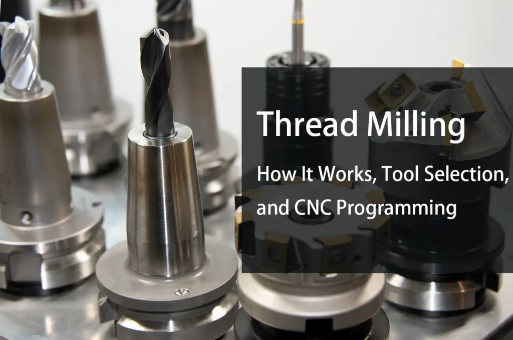
Thread milling is a CNC machining process that uses a rotating milling cutter to generate internal or external threads through a helical toolpath. Unlike tapping, where a tap forms the thread along its own axis, thread milling creates the thread profile by combining circular interpolation in the XY plane with axial movement in Z.
This makes thread milling useful when a part requires precise threads, difficult-to-machine materials, multiple thread sizes, or greater control over the threading process.The process is especially relevant for CNC milling centers because the same machine can perform the holemaking and threading operations without changing to a dedicated tapping process.
What Is Thread Milling?
Thread milling is a machining process in which a thread mill moves along a helical path while rotating at the spindle. The cutter travels around the inside or outside diameter of the thread while simultaneously moving along the thread axis by one pitch per revolution.
For an internal thread, for example, the cutter enters the prepared hole, moves around the thread diameter, and advances axially at a rate corresponding to the thread pitch.
Haas describes this motion as a combination of a standard G02 or G03 circular interpolation move with a simultaneous Z-axis movement. One circular revolution combined with the appropriate axial movement produces one thread pitch.
The basic relationship is:
Pitch = 1 ÷ Threads Per Inch (TPI)
For example, an 8 TPI thread has a pitch of 0.125 in.
Metric threads use the specified pitch directly. A thread specified as M10 × 1.5, for example, has a 1.5 mm pitch.
How Does Thread Milling Work?
The thread milling process generally involves four stages:
- Preparing the hole or outside diameter
- Positioning the thread mill
- Cutting the helical thread path
- Retracting the tool and inspecting the thread
For internal threads, the starting hole must provide sufficient clearance for the cutter. The thread mill then moves along a circular path while simultaneously moving in Z.
The tool does not need to have the same diameter as the finished thread. This is one of the fundamental differences between thread milling and tapping.
Helical Interpolation
The key movement in thread milling is helical interpolation.
The CNC control combines:
- Circular movement in X and Y
- Linear movement in Z
- Spindle rotation
- Programmed feed rate
The circular motion establishes the thread diameter, while the Z-axis movement establishes the pitch.
For a right-hand internal thread, the direction of the circular and axial movements must be programmed correctly. The exact G-code implementation depends on the CNC control and machine configuration, so programming should follow the control manufacturer’s conventions rather than assuming one universal code sequence. Haas provides G02/G03 examples specifically for thread milling.
Thread Milling vs. Tapping
Thread milling and tapping can both produce internal threads, but the cutting mechanics are different.
| Factor | Thread Milling | Tapping |
|---|---|---|
| Cutting method | Helical milling | Thread-forming/cutting tool follows thread pitch |
| Tool diameter | Smaller than finished thread | Approximately matches thread size |
| Machine motion | Circular + axial interpolation | Axial feed synchronized with spindle |
| Thread direction | Can be controlled through toolpath | Determined by tap |
| Tool flexibility | One tool can cover multiple diameters within its range | Usually dedicated to a thread size |
| Blind holes | Often useful | Possible, but chip evacuation can be more difficult |
| Tool breakage | Generally easier to manage | Broken taps can be difficult to remove |
| Machine requirement | CNC interpolation capability | Tapping cycle / synchronized spindle capability |
| Production speed | Depends heavily on thread size and strategy | Often very fast for repetitive threading |
Thread milling is not automatically better than tapping.
Tapping can be highly productive for large quantities of identical threads. Thread milling becomes more attractive when flexibility, thread quality, difficult materials, blind holes, or reduced tool inventory are important considerations.
Seco notes that thread milling can use the same tool for different thread diameters within its applicable range and for both left- and right-hand threads.
Advantages of Thread Milling
One Tool Can Cover Multiple Thread Sizes
A single-form thread mill can often machine multiple thread diameters when the cutter geometry and programming range allow it.
This is particularly useful for prototype work or production environments with many different thread specifications.
Harvey Performance describes single-form thread mills as a versatile option for producing several 60° thread forms, including common UN and metric threads.
The exact usable range still depends on the cutter geometry, thread profile, diameter, and required thread depth.
Better Control Over Thread Size
Thread milling provides another advantage during inspection and process adjustment: the final thread diameter is controlled by the toolpath.
If a finished thread needs a small dimensional correction, the toolpath can potentially be adjusted without changing to a different nominal tap size.
This does not eliminate the need for proper tool selection or inspection. It simply gives the machinist more control over the cutting path.
Useful for Blind Holes
Thread milling can be advantageous for blind holes because the cutter does not have to travel through the entire hole in the same way a conventional tap does.
The machining path can be programmed to stop at a controlled depth.
However, the required clearance below the finished thread still has to be considered. The cutter needs enough space to enter, interpolate, and retract safely.
Lower Risk From Tool Breakage
A broken tap inside an expensive component can be difficult to remove, particularly when machining hardened or difficult materials.
Thread milling does not make tool breakage impossible, but the smaller cutter and milling-based process can make a failed tool easier to deal with than a broken tap in some applications.
This is one reason thread milling is often considered for high-value components where recovery from a tooling failure matters.
Suitable for Difficult Materials
Thread milling can also be useful when machining materials that create problems for conventional tapping.
Seco specifically identifies thread milling as an option for machining threads in hardened materials and difficult applications.
The actual result depends on:
- Material grade
- Hardness
- Cutter material
- Coating
- Tool geometry
- Cutting parameters
- Coolant
- Thread depth
- Machine rigidity
There is no universal thread-milling parameter that works across all materials.
Types of Thread Mills
Thread mills are available in several configurations. The correct choice depends on the thread profile, diameter, depth, material, and production requirements.
Single-Form Thread Mills
A single-form thread mill cuts one thread form per revolution.
These tools are flexible because the same cutter can often be programmed for different thread diameters within its usable range.
They are particularly useful for:
- Prototypes
- Low-volume production
- Mixed thread sizes
- Maintenance work
- Parts with multiple thread specifications
The trade-off is productivity. A single-form cutter may require more interpolation passes than a multi-form cutter.
Multi-Form Thread Mills
Multi-form thread mills have multiple cutting teeth designed to engage more of the thread profile during the operation.
They can improve productivity in suitable production applications.
However, tool selection becomes more specific. The cutter must match the intended thread geometry and operating conditions.
For high-volume production, the higher productivity can justify using a more dedicated thread-milling tool.
Indexable Thread Mills
Indexable thread mills use replaceable cutting inserts instead of a solid carbide body with a permanently ground cutting edge.
They can be advantageous for:
- Larger thread diameters
- Production environments
- High material removal requirements
- Applications where insert replacement is preferred over complete tool replacement
The appropriate system depends heavily on thread diameter, thread profile, machine capability, and cutting conditions.
Thread Milling Tool Selection
Choosing the cutter should start with the thread specification rather than the tool itself.
Important variables include:
Thread Diameter
The finished thread diameter determines whether the selected cutter can physically access the feature and produce the required profile.
Smaller cutters can provide greater flexibility, but smaller cutting diameters also generally mean a less rigid tool.
Sandvik’s thread milling guidance specifically notes that a smaller cutting diameter can help achieve higher thread quality, while tool selection must still account for application conditions.
Thread Pitch
The cutter and toolpath must match the required pitch.
For example:
- M8 × 1.25 → 1.25 mm pitch
- M12 × 1.75 → 1.75 mm pitch
- 1/4-20 UNC → 20 TPI
- 1/2-13 UNC → 13 TPI
The programmed axial movement must correspond to the specified pitch.
Thread Form
The cutter must match the required thread form.
Common examples include:
- Metric
- UN/UNC/UNF
- NPT
- Other specialized thread profiles
Do not assume that one thread mill can produce every thread form.
Thread Depth
Tool reach matters for deep threads.
A long tool may be required for a deep feature, but increasing tool stickout can reduce rigidity and increase the risk of deflection or vibration.
Material
Tool material and coating should be selected according to the workpiece.
Aluminum, stainless steel, titanium, hardened steel, and nickel-based alloys behave differently during cutting.
Cutting data should therefore come from the selected tool manufacturer’s recommendations and then be adjusted for the actual machine, workholding, tool stickout, and application.
Thread Milling Cutting Parameters
Thread milling parameters should not be copied from a generic chart without considering the actual application.
Important variables include:
- Cutting speed
- Spindle speed
- Feed rate
- Feed per tooth
- Radial engagement
- Axial depth
- Number of passes
- Tool diameter
- Thread pitch
- Workpiece material
One particularly important point is feed calculation.
Thread milling involves both tool rotation and programmed circular motion. The required feed must therefore be calculated correctly for the tool and machine control rather than treating the operation like a conventional straight milling pass.
Sandvik recommends using small feed-per-tooth values for thread milling when the goal is high thread quality and emphasizes calculating the appropriate machine feed to maintain the intended cutting load.
Thread Milling Toolpath Strategy
Toolpath design has a direct effect on thread quality and tool loading.
The cutter should not simply be plunged aggressively into the thread.
A controlled entry and exit reduces sudden engagement.
Sandvik recommends smooth roll-in and roll-out movements for thread milling rather than abrupt engagement.
For difficult applications, multiple infeed passes may also be used.
This can be useful when:
- The material is difficult to machine
- The thread is deep
- The cutter is relatively small
- Tool deflection is a concern
- Surface finish requirements are high
The appropriate number of passes depends on the tool and application.
Internal vs. External Thread Milling
Thread milling can be used for both internal and external threads.
Internal Thread Milling
Internal thread milling is commonly used for threaded holes.
The basic sequence is:
- Drill or interpolate the starting hole.
- Position the thread mill at the correct depth.
- Enter the thread path.
- Interpolate the thread diameter.
- Move axially by the thread pitch.
- Complete the required thread depth.
- Retract the cutter.
The starting hole diameter is important because it determines how much material the thread mill needs to remove.
External Thread Milling
External thread milling uses a similar helical principle, but the cutter works around the outside diameter.
The workpiece must provide enough clearance for the tool and spindle movement.
The exact toolpath direction depends on:
- Thread hand
- Tool rotation
- Cutter position
- CNC control
- Climb/conventional milling strategy
For this reason, the actual CNC program should be verified through simulation and the machine/control documentation before production.
Thread Milling Problems and Troubleshooting
Poor Thread Surface Finish
Possible causes include:
- Excessive feed
- Tool deflection
- Incorrect cutter diameter
- Poor toolpath entry
- Excessive radial engagement
- Tool wear
- Insufficient machine rigidity
A smaller cutting diameter can help thread quality in some applications, but reducing tool diameter too far can also reduce rigidity.The entire cutting system needs to be considered.
Oversized or Undersized Threads
Possible causes include:
- Incorrect toolpath diameter
- Tool wear
- Incorrect cutter diameter
- Tool deflection
- Incorrect machine compensation
- Programming error
Because thread milling relies on the programmed circular path, dimensional correction can often be made through toolpath or compensation adjustments, depending on the machine control and programming method.
The finished thread should still be verified with the appropriate gauge or measurement method.
Chatter and Vibration
Chatter can become more noticeable when:
- Tool stickout is excessive
- The cutter is too small for the required depth
- Workholding is weak
- Cutting parameters are inappropriate
- The machine setup lacks rigidity
Reducing unsupported tool length is usually preferable to simply lowering cutting speed.
Tool Breakage
Thread mills are relatively small compared with many conventional milling cutters, so tool rigidity matters.
Common contributors include:
- Excessive engagement
- Incorrect feed
- Poor chip evacuation
- Excessive tool stickout
- Incorrect thread depth
- Improper entry or exit
- Wrong cutting data for the material
For difficult applications, reducing the load through multiple passes may provide a more stable process. Sandvik also identifies multiple infeed passes as an option for demanding thread-milling applications.
When Should You Use Thread Milling Instead of Tapping?
Thread milling is particularly worth considering when:
- The component has expensive material or high part value.
- Different thread sizes are required.
- Blind holes are involved.
- The material is difficult to tap.
- Thread dimensional control is important.
- Left- and right-hand threads are required.
- Tool inventory needs to be reduced.
- The CNC machine has suitable interpolation capability.
Tapping may remain the better choice when:
- The same thread is produced in very high quantities.
- Cycle time is the primary concern.
- The material is straightforward to tap.
- Existing production equipment is already optimized for tapping.
The right choice is therefore application-dependent rather than a simple question of which process is “better.”
Thread Milling Best Practices
For consistent results, consider the following:
1. Start With the Thread Specification
Define:
- Diameter
- Pitch
- Thread form
- Tolerance
- Thread depth
- Internal or external configuration
before selecting the cutter.
2. Minimize Tool Stickout
Use only the reach required by the feature.
Long unsupported tools are more susceptible to deflection and vibration.
3. Use Manufacturer Cutting Data
Start with the tool manufacturer’s recommended parameters for the specific cutter and workpiece material.
Then adjust based on:
- Machine rigidity
- Toolholder
- Workholding
- Tool stickout
- Coolant
- Actual cutting behavior
4. Control Entry and Exit
Avoid abrupt tool engagement.
A smooth roll-in and roll-out path can reduce sudden cutting loads.
5. Verify the Toolpath
Thread milling combines circular and axial movement, so programming errors can produce incorrect thread pitch, diameter, or hand.
Use simulation when available.
6. Inspect the Finished Thread
Visual inspection is not sufficient for critical threads.
Depending on the requirement, inspection may involve:
- GO/NO-GO gauges
- Thread plug gauges
- Thread ring gauges
- CMM measurement
- Optical measurement
- Functional assembly testing
The inspection method should match the drawing requirement and thread tolerance.
Thread Milling vs. Tapping: Which Process Is Better?
Neither process is universally better.
Thread milling provides greater flexibility and control, particularly for complex parts, difficult materials, and varied thread sizes. Tapping can be faster and simpler for high-volume production of standardized threads.
A useful way to make the decision is to consider five factors:
| Consideration | Favor Thread Milling | Favor Tapping |
|---|---|---|
| Multiple thread sizes | ✓ | |
| Difficult materials | ✓ | |
| High-value components | ✓ | |
| Flexible thread sizes | ✓ | |
| High-volume identical threads | ✓ | |
| Maximum threading speed | ✓ | |
| Simple standardized parts | ✓ | |
| Blind-hole control | ✓ | |
| Existing tapping process | ✓ |
The best process is the one that provides the required thread quality and production economics with an acceptable level of process risk.
FAQ
F: What is thread milling?
Q: Thread milling is a CNC machining process that uses a rotating cutter and helical interpolation to create internal or external threads.
F: Is thread milling better than tapping?
Q: Not necessarily. Thread milling provides more flexibility and can be useful for difficult materials, blind holes, varied thread sizes, and high-value parts. Tapping can be faster for high-volume production of identical threads.
F: Can thread mills cut both internal and external threads?
Q: Yes. Suitable thread mills and toolpaths can be used for both internal and external threading, provided the cutter geometry and machine setup are appropriate.
F: Can one thread mill make different thread sizes?
Q: Some single-form thread mills can machine multiple thread diameters within their design range. The cutter geometry, thread form, pitch, and required diameter must all be compatible.
F: What CNC machines can perform thread milling?
Q: A CNC machine needs suitable circular interpolation and coordinated axial movement. The exact capability depends on the machine control, software, and configuration. Haas, for example, documents thread milling using coordinated G02/G03 circular motion with Z-axis movement.
F: Is thread milling suitable for hard materials?
Q: It can be. Thread milling is used for difficult and hardened materials, but cutter selection and cutting parameters need to be matched to the material and machine setup.
Conclusion
Thread milling creates threads through a controlled helical milling path rather than by forcing a tap through the material. Its main value is flexibility: the same CNC platform can handle different thread sizes and configurations while giving the programmer direct control over the cutting path.
For production planning, the important variables are not just the thread size. Tool diameter, pitch, cutter geometry, material, thread depth, machine rigidity, tool stickout, cutting parameters, and toolpath strategy all affect the final result.
For CNC manufacturers, thread milling is therefore best treated as a machining strategy rather than simply another threading tool. The right application starts with the thread specification and works backward to the cutter, machine, and cutting conditions.