

Facing on a milling machine, commonly called face milling, is the process of producing a flat surface perpendicular to the machine spindle axis. The primary cutting action occurs on the face of the rotating cutter rather than on its periphery.
A facing milling machine is simply a milling machine (manual or CNC) configured and tooled for this operation. Vertical machining centers are the most common platform because the spindle naturally points perpendicular to the table.
How Face Milling Works
The cutter axis is oriented at 90° to the surface being machined. Multiple cutting edges—usually indexable carbide inserts mounted on a face-mill body—engage the workpiece as the tool rotates and the table feeds beneath it.
Each insert removes a small chip. Because several inserts are in cut simultaneously, material removal rate is high relative to the axial depth of cut. The resulting surface is flat, with flatness and surface finish determined by machine rigidity, insert condition, lead angle, and cutting parameters.
Face milling is typically used to:
- Establish a reference plane
- Remove stock from large flat areas
- Square a workpiece before further operations
- Produce finished surfaces that require good flatness and moderate surface roughness
Face Milling versus Peripheral Milling
The distinction is kinematic.
In face milling the spindle is perpendicular to the machined surface and the main cutting edges lie on the tool face. Axial depth of cut is usually modest; radial engagement can be a large percentage of the cutter diameter.
In peripheral (or side) milling the spindle is parallel to the machined surface and cutting occurs primarily on the cylindrical periphery of the tool. This mode is used for walls, slots, contours, and deeper features.
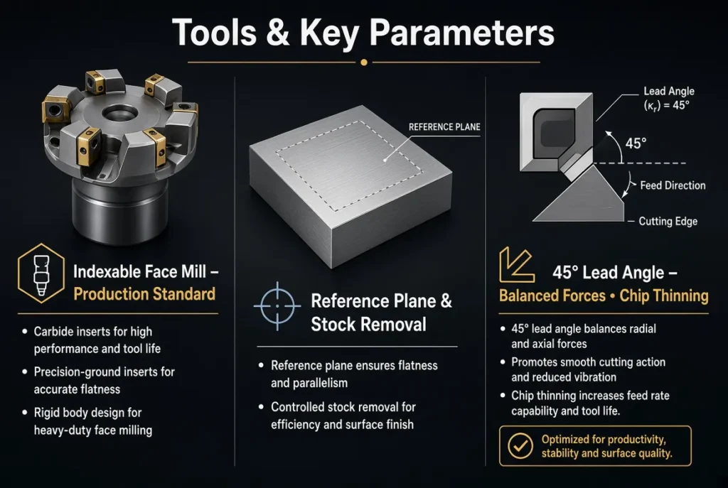
A face mill cannot efficiently produce a true 90° shoulder unless it is a 90° shoulder mill. Most general-purpose face mills use a 45° lead angle, which improves force distribution and allows higher feed rates through chip thinning.
Tools Used for Facing
Indexable face mills The standard production tool. A steel or carbide body holds multiple replaceable inserts around the periphery and face. Insert geometry (rake, clearance, nose radius, lead angle) is selected for the material and whether the priority is roughing or finishing.
Shell mills Larger-diameter modular cutters mounted on an arbor. Used when a wide surface must be covered in fewer passes.
Fly cutters Single-point tools. Inexpensive and capable of very fine finishes on small-to-medium surfaces, but slow and sensitive to vibration.
High-feed face mills Shallow axial depth of cut combined with very high feed per tooth. Productive for roughing when machine power and rigidity allow.
Insert materials range from coated carbide (most common) to ceramics, CBN, or PCD depending on workpiece hardness and volume.
Key Cutting Parameters
- Axial depth of cut (ap) Roughing: typically 1–5 mm depending on machine power and insert strength. Finishing: 0.1–0.5 mm (or less) to achieve the required flatness and finish.
- Radial engagement (ae) Often 60–90 % of cutter diameter for efficient use of the tool. Full-width cuts are possible but increase radial forces.
- Feed per tooth (fz) Adjusted for lead angle. A 45° lead angle produces chip thinning, so programmed feed is increased to maintain the desired chip thickness at the cutting edge.
- Cutting speed (Vc) Determined by insert grade and workpiece material. Coated carbide on steel is commonly in the 100–250 m/min range; aluminum allows significantly higher speeds.
Climb milling is preferred on CNC machines for better surface quality and tool life when the setup is rigid.
Machine Requirements
Any milling machine with adequate spindle power, rigidity, and a perpendicular spindle-to-table relationship can perform face milling. Practical requirements include:
- Sufficient horsepower and torque at the intended spindle speed
- Stable workholding that resists the combination of axial and radial forces
- Accurate Z-axis control for consistent depth of cut
- Effective chip evacuation and coolant delivery
Vertical machining centers dominate face-milling work because of accessibility and gravity-assisted chip flow. Horizontal machines are used when the part geometry or production volume favors that orientation.
Practical Considerations and Limitations
Surface flatness is limited by machine geometry, thermal stability, and residual stress in the workpiece. Large plates may distort after material removal; sequential light finishing passes or stress-relief strategies are sometimes required.
Insert height variation and cutter runout directly affect surface finish. Regular inspection and consistent insert seating are necessary for repeatable results.
Face milling is inefficient for deep cavities, narrow slots, or complex 3D contours—those features are better addressed by end milling or other strategies.
Summary Definition
A facing milling machine is a milling machine equipped and programmed to perform face milling: the generation of a flat surface perpendicular to the spindle axis by the action of a rotating multi-insert cutter. The process is defined by tool orientation, insert geometry, and controlled axial and radial engagement. It remains the primary method for producing accurate reference planes and large flat surfaces on prismatic components.
FAQ
Q: Can any milling machine do face milling?
A: Yes, provided the spindle can be oriented perpendicular to the surface and the machine has sufficient rigidity and power for the chosen cutter and depth of cut.
Q: Why do most face mills use a 45° lead angle?
A: The 45° angle balances axial and radial forces, reduces vibration tendency, and allows higher programmed feeds through chip thinning while still producing an acceptable surface.