
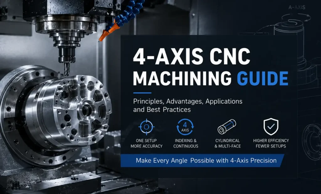
4 axis CNC machining adds one rotary axis to the three linear axes of a standard milling machine. The tool still moves in X, Y, and Z. The workpiece can rotate about a fourth axis—most often the A-axis, which rotates around X—so multiple faces or a cylindrical surface can be reached without removing the part from the fixture.
The extra axis does not make the machine a 5-axis system. The spindle orientation stays fixed. The part rotates; the tool does not tilt.
What 4 Axis CNC Is
A typical 4 axis CNC mill is a vertical or horizontal machining center fitted with a CNC rotary table, trunnion, or chuck. The controller treats rotation as a programmed axis rather than a separate indexer box.
The usual configuration on a vertical mill is:
- X, Y, Z — linear tool motion
- A — workpiece rotation about X
Other rotary labels (B or C) appear depending on how the table is mounted, but the engineering idea is the same: one controlled rotation plus three linear axes.
4 axis CNC is used in two distinct ways: indexing (position, lock, then cut) and continuous interpolation (rotation and linear motion at the same time). Those modes solve different problems and should not be treated as interchangeable.
How 4 Axis CNC Works
The part is clamped on the rotary axis so that the intended rotation center is aligned with the machine’s A-axis. After a single work offset is established, the controller can rotate the part to a new face or sweep it while the cutter moves.
In a multi-face housing, the machine mills the top at 0°, indexes 90°, mills the side, and continues around the part. All features share the same datum. That removes the stack-up that appears when the same part is unclamped and re-indicated on a 3-axis vise for each face.
On a shaft or cylinder, continuous A-axis motion combined with Z or X feed can generate a helix, cam profile, or wrapped engraving. The controller interpolates all four axes so the tool stays on the programmed path as the part turns.
Workholding must keep the part rigid through rotation. Common setups include a rotary chuck with tailstock support, a trunnion fixture, or a tombstone mounted on a horizontal rotary table. Clearance to the table, vise jaws, and toolholder must be checked at every planned angle.
Indexed vs Continuous Motion
Indexed 4-axis (often called 3+1) rotates the part to a fixed angle, applies a brake or lock, then machines with only X, Y, and Z moving. Rigidity is high because the rotary axis is stationary during the cut. Programming is closer to 3-axis work plus positioning moves. This mode is the workhorse for prismatic parts: housings, valve bodies, flanges with bolt patterns, and features on four sides.
Continuous 4-axis interpolates A with the linear axes while the tool is cutting. It is required for helical grooves, worm geometry, cam lobes, and wrapped 2D toolpaths on a cylinder. Programming needs a CAM system that can generate simultaneous rotary motion and a post-processor that matches the machine kinematics. Cutting rigidity is usually lower than in locked-index mode because the rotary drive is live under load.
A machine advertised as “4 axis” may only index. True simultaneous 4-axis control is a controller and CAM capability, not just a rotary table bolted to the mill.
4 Axis vs 3 Axis and 5 Axis
3-axis CNC machines one primary orientation per setup. Multi-sided parts require re-fixturing. Feature-to-feature accuracy across faces depends on how well each new setup is located.
4-axis CNC keeps one setup for features around a single rotation axis. It is efficient for four-sided prismatic work and for geometry that wraps around a cylinder. The tool remains vertical (or fixed in orientation). Compound angles that need the tool to tilt out of that plane are outside its reach without special fixtures.
5-axis CNC adds a second rotary axis so the tool or the part can tilt as well as rotate. That enables undercuts, deep cavities with short tools, and freeform surfaces such as impellers or orthopedic contours. Cost, programming effort, and collision risk are higher.
4-axis sits between the two: more access and fewer setups than 3-axis, less geometric freedom and usually lower cost than simultaneous 5-axis.
Advantages
Fewer setups reduce handling time and the positional error that accumulates when a part is reclamped. Features on different faces share one datum, which improves relationship tolerances such as hole patterns around a cylinder or pockets on adjacent walls.
Continuous mode makes helical and cam geometry practical without custom form tools or multiple operations. Wrapped engraving and cylindrical patterning become CAM operations rather than special machines.
For the right parts, cycle time drops because index moves replace full teardown and re-indication. Tool access can improve on some faces because the part can be rotated into a clearer attitude than a fixed vise allows.
Limitations
The spindle does not tilt. Undercuts and compound-angle features that require a second rotary axis still need 5-axis or a dedicated fixture. Deep pockets on a rotated face can still force long tools if the rotary setup creates overhang.
Rotary accuracy and stiffness limit how aggressive the cut can be. Heavy milling far from the rotation center multiplies torque and can excite chatter. Tailstock support or shorter stick-out is often required on long parts.
Programming and simulation effort rise, especially for continuous toolpaths. Collision checking must include the rotary table, chuck jaws, tailstock, and toolholder at every angle. A 4-axis fixture is more involved than a standard vise setup.
Machine and fixture cost sit above 3-axis. If the part is a simple plate or a single-sided prism, the extra axis adds little value.
Typical Applications
Common work includes multi-face housings and manifolds, flanges and hubs with angular hole patterns, shafts with flats or cross-holes, cams and helical grooves, cylindrical engraving, and medium-complexity parts that would otherwise need three or four 3-axis setups.
Industries that use 4 axis CNC regularly include industrial machinery, automotive, oil and gas fittings, and general precision components where cylindrical or four-sided geometry is common but full 5-axis surfaces are not.
Programming and CAM Considerations
Indexed work can often be programmed as a sequence of 3-axis operations with A-axis positioning moves and separate work planes or tool orientations in CAM. Continuous work needs simultaneous 4-axis toolpaths and a post that outputs coordinated A-axis motion.
Part zero for indexing is usually a convenient face or centerline that stays consistent as the part turns. Continuous wrapping typically uses the rotation center as the reference so the CAM wrapper or rotary toolpath maps correctly to diameter.
Always simulate the full rotary envelope. A path that is safe at 0° can collide at 90° with the chuck or tailstock. Confirm that the post matches the machine’s axis direction, scaling, and rotary direction conventions before the first chip.
Practical Tips and Best Practices
Align the rotary centerline carefully. Runout or an offset rotation axis shows up as wall thickness error and mismatched features after indexing.
Support long parts with a tailstock or steady rest so cutting forces do not wind up the rotary drive. Keep tool stick-out short when milling on a rotated face; the effective lever arm includes fixture height plus part radius.
Use indexed mode when faces are discrete and rigidity matters. Use continuous mode only when the geometry actually requires simultaneous rotation.
Plan workholding so jaws and clamps do not occupy a face that must be cut later. Tombstones and multi-station fixtures increase throughput but raise collision and balance issues.
Verify angular positioning on the first article with a feature that can be measured from the same datum used in CAM. Do not assume the programmed angle equals the machined angle without checking the rotary encoder, backlash, and fixture deflection.
Selection Considerations
Choose 4 axis CNC when the part needs features around one rotation axis or on four sides, and when reducing setups will improve either cycle time or inter-feature accuracy. Stay on 3-axis when the geometry is single-sided or easily flipped in a vise. Move to 5-axis when undercuts, compound tool angles, or freeform surfaces dominate.
Evaluate the actual machine: indexing-only rotary tables do not replace simultaneous 4-axis control. Match CAM, post-processor, and fixture design to the mode you intend to run.
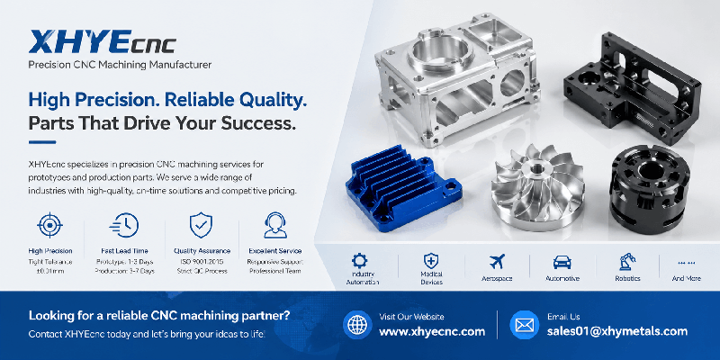
XHYE supplies precision CNC machining services covering multi-axis milling, turning, and related processes for complex geometries and tight-tolerance requirements, including 4-axis work on multi-face and cylindrical parts. Capabilities include common engineering materials and both prototype and production volumes. Technical consultation for specific projects is available at xhyecnc.com.