

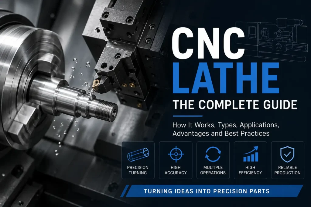
A CNC lathe is a computer-controlled machine tool that rotates the workpiece while a cutting tool removes material. The process is called turning. It is used to generate surfaces of revolution: cylinders, tapers, faces, grooves, threads, and related features that share a common axis.
CNC means Computer Numerical Control. A controller executes a program—usually G-code from CAD/CAM—and coordinates spindle speed, axis motion, tool changes, and auxiliary functions. The operator sets up the job; the machine then repeats the path with the consistency of the program, not the consistency of hand-cranked slides.
A CNC lathe is not the same thing as a CNC mill. On a lathe the part spins. On a mill the tool spins. That single difference determines which geometries each machine produces efficiently.
How a CNC Lathe Works
Bar stock, a sawn blank, or a forging is clamped in a chuck or collet on the main spindle. The spindle rotates. Tools on a turret, gang slide, or tool post feed into the rotating work.
On a basic two-axis lathe the tool moves in two directions:
- X — toward or away from the centerline (diameter)
- Z — along the spindle axis (length)
Facing cuts across the end of the part and establishes a length datum. Turning reduces the outside diameter. Boring opens an inside diameter. Grooving, threading, and parting use the same axes with different inserts and cycles.
The controller can run constant surface speed so cutting speed stays roughly constant as diameter changes, or constant RPM when that is safer for the chuck and tooling. Canned cycles handle repetitive stock removal: rough turning, finish turning, grooving, and multi-pass threading. M-codes start coolant, index the turret, reverse the spindle, and open or close the chuck.
The workflow is CAD model → CAM toolpaths and post-processed G-code → setup (workholding, tools, offsets) → prove-out → production. Accuracy depends as much on chuck runout, tool-nose radius, thermal drift, and work support as it does on the control.
Main Components
The headstock contains the spindle, bearings, and drive. Spindle power, maximum speed, and chuck capacity set how large and how heavy a cut the machine can take.
The chuck or collet holds the work. Three-jaw chucks are common for general turning. Collets are used for bar work and better concentricity on smaller diameters. Hydraulic or pneumatic actuation is standard on production machines.
The bed and ways carry the carriage or turret. Slant-bed turning centers are the usual production layout: chips fall away from the ways, and the turret can sit closer to the spindle centerline. Flat-bed or heavy engine-lathe structures remain useful when swing, mass, or very large diameters dominate.
The turret indexes multiple turning, boring, threading, and parting tools. Live-tool stations add driven milling or drilling. A tailstock supports the free end of long parts. Many production machines add a sub-spindle so the part can be transferred and finished on the back side without a second setup.
The CNC control interpolates the axes, stores offsets, and runs the program. Tool-nose radius compensation matters on finish profiles; ignoring it leaves corner errors on tapers and radii.
What a CNC Lathe Can Do
Typical operations include:
- Facing and turning (OD and ID)
- Taper turning
- Grooving and parting-off
- Single-point threading (external and internal)
- Drilling and boring on center
- Knurling
- With live tooling and C-axis: flats, cross-holes, keyways, and light milling
Bar feeders allow continuous production from stock. Sub-spindles allow complete parts in one cycle when both ends must be machined.
Types of CNC Lathes
“CNC lathe” is a family name, not a single machine architecture.
2-axis CNC lathe
X and Z only. Best for shafts, bushings, fittings, and threaded parts that do not need off-center milling. Lowest programming complexity and usually the lowest hourly rate.
Turning center with live tooling
Adds C-axis spindle positioning and driven tools. Cross-holes, wrench flats, and light milling can stay on the lathe. A Y-axis allows off-center milling. This is the common “done-in-one” machine for mixed turned parts that would otherwise visit a mill.
Mill-turn / multi-tasking machine
Combines a turning spindle with a more capable milling spindle or B-axis head. Used when turning and substantial milling must stay in one clamping. Cost and programming effort are higher than a standard turning center.
Swiss-type (sliding-headstock) lathe
The bar feeds through a guide bushing. The headstock slides in Z so the cut happens next to the support point. That architecture reduces deflection on long, small-diameter parts. Typical bar capacity is much smaller than a chucker lathe. Setup is longer; the payoff is on slender, high-volume precision work.
Vertical turning lathe (VTL)
The part stands on end. Used for large-diameter, heavy rings, wheels, and disks that are awkward on a horizontal spindle.
A “CNC lathe” and a “CNC turning center” are often used as synonyms. In plant language, a turning center usually means a slant-bed production machine, often with live tools; a CNC engine lathe often means a heavier, larger-swing machine derived from traditional lathe construction.
CNC Lathe vs CNC Mill
| Factor | CNC lathe | CNC mill |
|---|---|---|
| What rotates | Workpiece | Cutting tool |
| Efficient geometry | Surfaces of revolution | Prismatic faces, pockets, 3D surfaces |
| Primary axes | X, Z (plus C/Y/B on advanced machines) | X, Y, Z (plus rotary axes on 4/5-axis) |
| Typical stock | Bar, round blank, forging | Block, plate, casting |
| Strength | Diameter control, roundness, threads about one axis | Flats, cavities, multi-face prismatic work |
If the part is a shaft, pin, bushing, or flange generated around one axis, turning is usually the shorter path. If the part is a housing, plate, or mold cavity, milling is usually the shorter path. Many production parts need both; that is why live-tool lathes and mill-turn machines exist.
Advantages
Turning generates round features efficiently because the part already rotates about the axis you care about. Concentric diameters, faces, and threads can share one setup datum. Material removal on round stock is typically faster than milling the same cylinder from square billet. Bar-fed cycles support unattended or lightly attended production. Live tooling and a sub-spindle can remove a second setup and the stack-up that comes with it.
Limitations
A 2-axis lathe cannot mill off-center features. Long, slender parts deflect or chatter unless a tailstock, steady rest, or Swiss-type bushing supports them. Live-tool milling on a lathe is usually lighter-duty than the same cut on a machining center. Large irregular blanks are often easier to clamp on a mill table than in a chuck. Adding axes, live tools, and sub-spindles increases setup time, collision risk, and CAM effort. Swiss-type machines are a poor fit for large diameters and frequent one-off changeovers.
Typical Applications
CNC lathes produce shafts, pins, bushings, flanges, fittings, valve components, fasteners, nozzles, and similar rotational parts. They are used in industrial machinery, automotive, energy, aerospace fittings, and medical instruments. Swiss-type work concentrates on small, high-volume parts such as bone screws, connectors, and injector components. VTLs handle large rotating parts that exceed practical horizontal chuck capacity.
Practical Tips
Choose the machine from diameter, length-to-diameter ratio, and whether milling must stay in the same setup. Support slender work. Use constant surface speed for finish consistency as diameter changes, and clamp maximum RPM so small diameters do not overspeed the workholding.
Separate roughing and finishing so insert geometry and feed match the cut. Include tool-nose radius compensation on finish profiles. For threads, confirm pitch, infeed method, and the cycle format used by that control (commonly a G76-style cycle on many Fanuc-type controls).
Concentricity starts at the chuck. Measure spindle and workholding runout before blaming the program. On the drawing, define which diameters and faces must stay concentric, whether the part is bar-fed or chucked, and which end is the primary datum.
When to Use a CNC Lathe
Use a 2-axis CNC lathe when the geometry is primarily turned. Add live tooling when flats, cross-holes, or light milling would force a second setup. Use Swiss-type equipment when the diameter is small, the part is long relative to diameter, and volume supports the setup. Use mill-turn when turning and substantial milling must remain in one clamp. Use a mill when the part is not generated around a single axis of rotation.
A CNC lathe is the right machine when rotation of the work is the most direct way to make the required surfaces—not because “CNC” is required for every round part.