
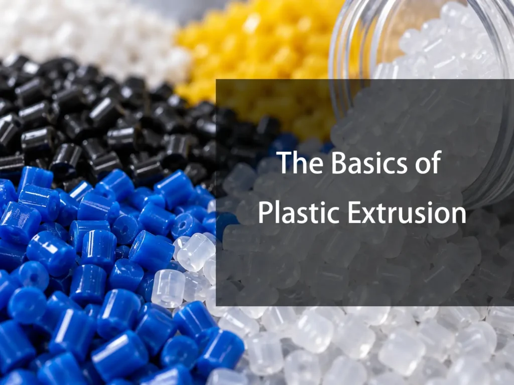
Plastic extrusion is one of the most widely used processes for producing continuous plastic products.Unlike injection molding, which fills a closed mold to produce individual parts, extrusion continuously pushes molten polymer through a shaped die. The resulting profile is then cooled, sized, and cut or wound according to the application.
The process looks simple from the outside: plastic enters one end of the machine and a finished profile comes out the other.
In practice, extrusion is a controlled interaction between polymer rheology, screw design, temperature, pressure, die geometry, cooling, and line speed. A small change in one of these variables can affect wall thickness, dimensions, surface appearance, output rate, or material stability.
Understanding the basics is useful not only for extrusion engineers, but also for designers specifying extruded plastic tubes, profiles, sheets, films, rods, and other continuous products.
What Is Plastic Extrusion?
Plastic extrusion is a continuous manufacturing process in which plastic resin is melted and forced through a die to produce a continuous shape.
The typical process is:
Plastic pellets → Feed system → Screw and barrel → Melt → Die → Cooling → Sizing → Haul-off → Cutting or winding
The die determines the basic cross-sectional geometry of the extruded product.
How Does Plastic Extrusion Work?
A conventional single-screw extrusion process can be understood as several connected stages.
1. Feeding the Plastic Resin
Most thermoplastic extrusion begins with pellets, granules, powder, or another prepared feedstock.The material enters the hopper and moves into the feed section of the barrel.At this stage, the polymer is still primarily solid.The screw must do more than simply transport the material. It needs to provide stable solids conveying so that the extruder receives a consistent amount of material.If feeding becomes inconsistent, output can fluctuate even if the screw speed remains constant.
Feed behavior depends on factors such as:
- Pellet size and shape
- Bulk density
- Material friction
- Moisture
- Feed-zone temperature
- Screw geometry
- Barrel design
For some difficult-to-feed materials, a grooved feed section or other specialized feeding arrangement may be used.
2. Melting the Polymer
As the solid material moves forward, it begins to soften and melt.
The heat comes from two main sources:
- External heaters around the barrel
- Mechanical energy generated as the screw works against the polymer
In many extrusion systems, mechanical energy from the motor is a major contributor to melt temperature. The screw transfers energy into the polymer through friction and viscous dissipation.This is an important point because extrusion is not simply a matter of setting the barrel heaters to a particular temperature.The screw is also a thermal-processing device.Increasing screw speed can increase shear and mechanical energy input. That can raise melt temperature even when the heater settings remain unchanged.This is one reason extrusion temperature must be monitored as a process variable rather than treated as a fixed machine setting.
3. Conveying and Compressing the Material
The screw is the central mechanical component of a conventional extruder.
A typical single screw is divided conceptually into three zones:
- Feed zone
- Compression or transition zone
- Metering zone
These zones do not operate independently. They form a continuous melting and conveying system.
Feed Zone
The feed zone normally has relatively deep screw channels.Its primary function is to accept and transport solid material.The polymer must move forward rather than simply rotate with the screw.
For a conventional smooth-barrel extruder, the interaction between the material, screw, and barrel surface is important for solids conveying. The feed material generally needs sufficient friction against the barrel to be carried forward by the screw flights.
Compression Zone
The screw channel becomes shallower through the compression section.This reduces the available volume and increases pressure on the polymer.At the same time, the material transitions from a mixture containing solid particles to predominantly molten polymer.The compression section is therefore where much of the melting process occurs.Screw geometry strongly affects how efficiently this happens.
A poorly matched screw can result in:
- Incomplete melting
- Excessive shear
- Unstable output
- Excessive melt temperature
- Poor mixing
- Material degradation
Metering Zone
The metering section normally has relatively shallow, consistent screw channels.By this point, the material should be substantially molten and homogeneous.The screw continues to convey the melt toward the die while building the pressure required to overcome resistance downstream.
The final pressure is affected by:
- Die geometry
- Screen pack
- Breaker plate
- Melt viscosity
- Screw geometry
- Screw speed
- Melt temperature
The metering section therefore plays an important role in stabilizing output before the polymer reaches the die.
What Is the Extrusion Die?
The die is the component that converts the pressurized polymer melt into the desired cross-sectional shape.This is one of the most important components in the extrusion line.
A simple way to think about the process is:
The screw creates and delivers the melt; the die shapes it.
The internal flow path of the die needs to distribute the melt consistently before it exits the die opening.A poorly designed or poorly balanced die can produce uneven output even when the extruder itself is operating correctly.
Why Die Design Matters
Polymer melt is not a simple Newtonian liquid.
Its viscosity changes with:
- Temperature
- Shear rate
- Molecular structure
- Material formulation
Beaumont Technologies describes viscosity as resistance to flow and notes that polymer flow behavior depends on shear rate and temperature.
This means that two sections of the same die may not experience identical flow conditions.
If the flow is poorly balanced, the extruded profile may show:
- Uneven wall thickness
- Dimensional variation
- Surface defects
- Distortion
- Unstable output
Die design therefore has to account for polymer flow behavior rather than simply reproducing the desired final profile in metal.
Die Swell: Why the Extrudate May Not Match the Die Opening
One of the basic concepts in plastic extrusion is die swell.
The polymer emerging from the die may expand relative to the dimensions of the die opening.This occurs because polymer chains become oriented and deformed while flowing through the die. Once the material exits the die and the constraints are removed, some of that stored deformation can recover.
The result is that:Die opening dimensions ≠ final product dimensions
The effect depends on factors such as:
- Polymer type
- Melt temperature
- Shear rate
- Die geometry
- Residence time
- Cooling conditions
Therefore, an extrusion die is normally designed based on the expected behavior of the polymer rather than simply machining the opening to the nominal product dimensions.This is one reason extrusion tooling requires process knowledge as well as dimensional accuracy.
Cooling the Extruded Plastic
After leaving the die, the polymer must be cooled enough to maintain its intended shape.This is more difficult than simply “making the plastic cold.”The product must lose enough heat to solidify while avoiding excessive distortion, residual stress, or dimensional variation.
Cooling methods depend on the product.
Common approaches include:
- Air cooling
- Water cooling
- Cooling tanks
- Chill rolls
- Vacuum sizing
- Calibrators
- Controlled cooling chambers
The cooling system is part of the dimensional-control system.
Plastics Today notes that cooling must remove heat without distorting product dimensions, and that cooling rate can influence production speed as well as product precision.
Sizing the Extruded Product
For some extrusion products, cooling alone is not sufficient to establish the final dimensions.A sizing system may be used.
This is particularly important for:
- Pipes
- Tubes
- Profiles
- Precision sections
For example, a vacuum calibration system can help hold a hot extruded profile against a sizing surface while the polymer cools.The basic sequence becomes:
Die → Hot profile → Calibration → Cooling → Stable dimensions
This allows the process to compensate for polymer shrinkage and die swell while the material is still deformable.
Haul-Off and Line Speed
After the product has been formed and sufficiently cooled, a haul-off system pulls it through the extrusion line.
The relationship between:
- Extruder output
- Die dimensions
- Cooling
- Haul-off speed
determines the final product dimensions.This is particularly important for products such as sheet, film, tubing, and profiles.If the haul-off speed changes while extrusion output remains constant, the amount of material per unit length changes.
What Controls Plastic Extrusion Quality?
Extrusion quality depends on several variables working together.
Temperature
Temperature affects polymer viscosity, melting behavior, pressure, output, and material stability.
Too little heat can result in:
- Incomplete melting
- High pressure
- Poor surface quality
- Unstable flow
Too much heat can result in:
- Material degradation
- Discoloration
- Volatile generation
- Changes in molecular weight
- Surface defects
Plastics Today identifies degradation, cooling limitations, sizing problems, and additive effects among the consequences of excessive heat.
Screw Speed
Screw speed affects:
- Output
- Shear
- Melt temperature
- Residence time
- Mixing
- Pressure
Increasing screw speed can increase production rate, but it can also increase mechanical energy input and melt temperature.
That creates a practical limitation:The maximum useful screw speed is not necessarily the maximum available screw speed.
If the polymer becomes too hot or the downstream cooling system cannot remove the required heat, increasing screw speed can reduce product quality rather than improve productivity.
Screw Geometry
Screw geometry must match the polymer and application.
Important variables include:
- Screw diameter
- Length-to-diameter ratio
- Channel depth
- Compression ratio
- Flight geometry
- Mixing sections
- Barrier sections
The length-to-diameter ratio, commonly written as L/D, describes the effective screw length relative to its diameter.Standard single-screw designs often use L/D values around 24:1, although shorter and longer designs are also used for specific applications.Different materials require different screw designs.A screw optimized for one polymer may not provide the same melting and mixing behavior with another.
Melt Pressure
Pressure develops because the screw is pushing the melt against resistance downstream.
That resistance comes from:
- Screen packs
- Breaker plates
- Adapters
- Die channels
- Die openings
- Melt viscosity
Melt pressure is therefore a useful indicator of extrusion stability.
A sudden pressure increase may indicate:
- Screen contamination
- Material degradation
- Excessive viscosity
- A partially blocked die
- Temperature changes
- Material changes
A sudden pressure decrease can also be significant and may indicate:
- Feeding problems
- Screw wear
- Leakage
- Material inconsistency
- A process change
Pressure should therefore be evaluated together with output, temperature, and screw speed rather than interpreted as an isolated number.
Residence Time and Material Degradation
Plastic does not simply pass through the extruder at a uniform speed.Material can remain in different regions of the machine for different lengths of time.Residence time becomes particularly important for heat-sensitive polymers.If the material experiences excessive temperature for too long, polymer degradation can occur.
Possible symptoms include:
- Discoloration
- Odor
- Black specks
- Gels
- Reduced mechanical properties
- Surface defects
- Unstable processing
This is why shutdown and startup procedures matter.
Residual polymer left at elevated temperature can degrade and later contaminate the extrusion stream.
Common Plastic Extrusion Problems
Uneven Wall Thickness
Uneven wall thickness can come from several sources:
- Die misalignment
- Uneven die flow
- Incorrect calibration
- Uneven cooling
- Material variation
- Drawdown
- Changes in line speed
The solution is not always to adjust the die.
The first step should be determining whether the variation originates from the melt, die, cooling system, or haul-off.
Surface Roughness
Poor surface quality can be caused by:
- Excessive shear
- Inappropriate melt temperature
- Material degradation
- Die contamination
- Poor die surface condition
- Unstable flow
The extrusion surface should therefore be evaluated together with melt temperature, pressure, screw speed, and die condition.
Melt Fracture
Melt fracture is a flow instability that can occur when polymer melt passes through the die at sufficiently high shear conditions.
It can produce a rough or distorted surface.
Possible responses include:
- Reducing shear rate
- Adjusting melt temperature
- Changing die geometry
- Changing processing conditions
- Using a material grade with more suitable rheology
The correct solution depends on the polymer and severity of the instability.
Output Variation
Output instability can originate upstream or downstream.
Potential causes include:
- Inconsistent feeding
- Material bulk-density variation
- Moisture
- Screw wear
- Temperature fluctuation
- Pressure changes
- Die restriction
- Cooling changes
For troubleshooting, output should be correlated with screw speed and melt pressure.
If output per screw revolution decreases over time, screw or barrel wear may become relevant. Plastics Today specifically recommends monitoring output per turn as a useful way to identify extrusion wear.
Single-Screw vs Twin-Screw Extrusion
Not all extrusion uses a single screw.
Single-screw extrusion
Single-screw extruders are widely used for continuous products such as:
- Pipe
- Tubing
- Profiles
- Sheet
- Film
- Wire coating
Their basic operation is relatively straightforward: the screw conveys, melts, and pressurizes the polymer.
Twin-screw extrusion
Twin-screw extruders use two screws operating within the barrel.
They are particularly useful where the process requires more intensive:
- Mixing
- Compounding
- Dispersion
- Material blending
- Additive incorporation
Twin-screw equipment can be configured in different ways depending on the material and process objective.
The important distinction is that the machine architecture is selected according to the required material processing, not simply the desired output shape.
Plastic Extrusion vs Injection Molding
Extrusion and injection molding both process thermoplastics, but their manufacturing logic is different.
| Feature | Plastic Extrusion | Injection Molding |
|---|---|---|
| Production mode | Continuous | Cyclic |
| Main forming component | Die | Mold cavity |
| Typical products | Tubes, profiles, sheet, film | Individual 3D parts |
| Material flow | Continuous through die | Shot injected into cavity |
| Primary output | Constant cross-section | Discrete geometry |
| Cooling | Usually after die exit | Inside mold |
| Typical tooling | Extrusion die | Injection mold |
Extrusion is particularly efficient when the desired geometry can be represented by a continuous cross-section.
Injection molding becomes more attractive when the component contains complex three-dimensional features such as bosses, ribs, snap fits, internal cavities, or varying wall geometry.
The two processes are therefore complementary rather than interchangeable.
Where CNC Machining Fits Into Plastic Extrusion
Although extrusion itself is a polymer-processing operation, precision machining is important in the production of extrusion tooling and downstream components.
Extrusion dies contain precision flow passages and openings that must produce the intended profile.
Machined components may include:
- Extrusion dies
- Die inserts
- Mandrels
- Calibration components
- Guide components
- Fixtures
- Cutting tools
- Downstream tooling
The challenge is not simply achieving the nominal CAD dimensions.
The tooling has to produce the required polymer flow after accounting for:
- Die swell
- Polymer shrinkage
- Melt temperature
- Flow resistance
- Cooling
- Material orientation
For precision tooling, CNC machining provides the dimensional control needed to manufacture complex metallic components.This is particularly relevant when the die contains tight-tolerance features, internal profiles, or multiple flow channels.The same principle applies to plastic components themselves. CNC machining can also be used when an extruded stock shape requires secondary machining for holes, slots, threads, mounting surfaces, or other features.Plastic machining has its own dimensional challenges because polymers have higher thermal expansion and are generally more elastic than metals.
FAQ
Q: How does a plastic extruder work?
A: A screw rotates inside a heated barrel to convey, compress, melt, mix, and pressurize the polymer. The molten material then passes through a die, where it takes the desired cross-sectional shape.
Q: Why does plastic swell after leaving the die?
A: Polymer melt can recover some of the deformation and molecular orientation generated while flowing through the die. As a result, the extrudate can expand relative to the die opening.
Q: What controls extrusion product dimensions?
A: Product dimensions depend on several interacting variables, including die geometry, melt temperature, material rheology, extrusion output, cooling, calibration, and haul-off speed.
Q: What is the difference between extrusion and injection molding?
A: Extrusion continuously forms a polymer through a die, while injection molding fills a closed mold cavity during individual production cycles. Extrusion is well suited to continuous profiles; injection molding is better suited to discrete three-dimensional parts.
Q: Can CNC machining be used with extruded plastic?
A: Yes. CNC machining can be used for secondary operations on extruded plastic stock, including drilling, milling, threading, slotting, and precision contouring. It is also used to manufacture extrusion tooling and associated fixtures.